Quadrature Encoder Offset Calibration for PMSM Motor
This example calculates the offset between the d-axis of the rotor and encoder index pulse position as detected by the quadrature encoder sensor. The control algorithm (available in the field-oriented control and parameter estimation examples) uses this offset value to compute an accurate and precise position of the d-axis of rotor. The controller needs this position to implement the field-oriented control (FOC) correctly in the rotor flux reference frame (d-q reference frame), and therefore, run the permanent magnet synchronous motor (PMSM) correctly.
Models
The example includes this model:
mcb_pmsm_qep_offset_f28035
mcb_pmsm_qep_offset_f280049C
For F28069M control card, LAUNCHXL-F28069M controller and LAUNCHXL-F28379D controller, refer to Quadrature Encoder Offset Calibration for PMSM (Motor Control Blockset).
You can use these models only for code generation. You can use the open_system command to open the Simulink® model. For example, use this command for a F28035 based controller:
open_system('mcb_pmsm_qep_offset_f28035.slx');
For the model names that you can use for different hardware configurations, see the Required Hardware topic in the Generate Code and Deploy Model to Target Hardware section.
Required MathWorks Products
To generate code and deploy model:
For the models: mcb_pmsm_qep_offset_f28035/ mcb_pmsm_qep_offset_f280049C
Motor Control Blockset™
Embedded Coder®
C2000™ Microcontroller Blockset
Fixed-Point Designer™
Generate Code and Deploy Model to Target Hardware
This section instructs you to generate code and run the motor by using open-loop control.
The example uses a host and a target model. The host model is a user interface to the controller hardware board. You can run the host model on the host computer. The prerequisite to use the host model is to deploy the target model to the controller hardware board.
The host model uses serial communication to command the target model and run the motor in an open-loop configuration. You can use the host model to control the motor rotations and validate the direction of rotation of motor. The Incorrect motor direction LED in the host model turns red to indicate that the motor is running in the opposite direction. When the LED turns red, you must reverse the motor phase connections (from ABC to CBA) to change the direction of rotation. The host model displays the calculated offset value.
Required Hardware
This example supports these hardware configurations. Use the target model name (highlighted in bold) to open the model for the corresponding hardware configuration, from the MATLAB® command prompt.
F28035 control card + DRV8312-C2-KIT inverter: mcb_pmsm_qep_offset_f28035
For connections related to the preceding hardware configuration, see F28069/F28035/F28335 Control Card Configuration.
F280049C control card + DRV8312-C2-KIT inverter: mcb_pmsm_qep_offset_f280049C
Complete the hardware connections.
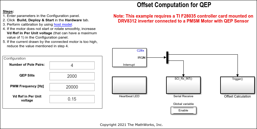
Open the target model for the hardware configuration that you want to use. If you want to change the default hardware configuration settings for the target model, see Model Configuration Parameters (Motor Control Blockset).
Update these motor parameters in the Configuration panel of the target model.
Number of Pole Pairs
QEP Slits
PWM Frequency [Hz]
Vd Ref in Per Unit voltage
Click Build, Deploy & Start on the Hardware tab to deploy the target model to the hardware.
Click the host model hyperlink in the target model to open the associated host model. You can also use the open_system command to open the host model. For example, use this command for a F28035 based controller:
open_system('mcb_pmsm_host_offsetComputation.slx');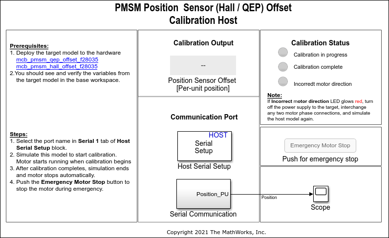
For details about the serial communication between the host and target models, see Host-Target Communication (Motor Control Blockset).
You can use the Time Scope in the host model to monitor the rotor position and offset values.
Set the parameter Port of the following blocks in the
mcb_pmsm_host_offsetComputationmodel to match the COM port of the host computer:mcb_pmsm_host_offsetComputation> Host Serial Setupmcb_pmsm_host_offsetComputation> Serial Communication > Host Serial Receivemcb_pmsm_host_offsetComputation> Serial Communication > SCI_TX > Host Serial Transmit
Click Run on the Simulation tab to run the host model. The motor runs and calibration begins when you start simulation. After calibration completes, simulation ends and the motor stops automatically.
See the Calibration Status section to know the status of calibration process:
Calibration in progress - LED turns orange when the motor starts running. Notice the rotor position and offset value variations in the Time Scope (the position signal indicates a ramp signal with an amplitude between 0 and 1). After calibration completes this LED turns grey.
Calibration complete - LED turns green when calibration completes. Then the Calibration Output field displays the computed offset value.
Incorrect motor direction - LED turns red if the motor runs in the opposite direction. Then the Calibration Output field displays the value "NaN." Turn off the DC power supply (24V) and reverse the motor phase connections from ABC to CBA. Repeat steps 5 to 8 and check if the Calibration complete LED is green. Verify that the Calibration Output field displays the offset value.
Note
This example does not support simulation.
During emergency, click the Emergency Motor Stop button to stop the motor immediately.
For examples that implement FOC using a quadrature encoder sensor, you must update the computed quadrature encoder offset value in the pmsm.PositionOffset parameter in the model initialization script linked to the example. For instructions, see Estimate Control Gains and Tune Control Parameters (Motor Control Blockset).