뱅뱅 온도 제어 시스템 모델링하기
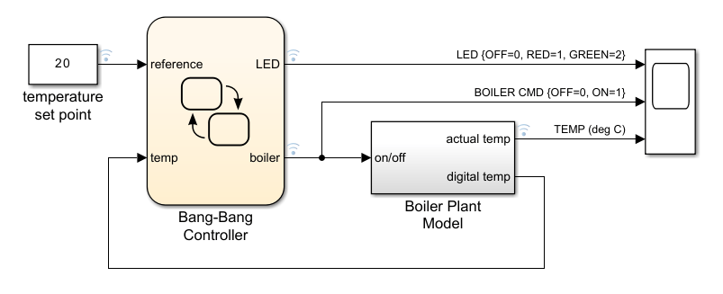
이 예제에서는 보일러의 온도를 조절하는 뱅뱅(Bang-Bang) 제어 시스템을 구축하는 방법을 보여줍니다. 이 예제에서는 보일러의 온도를 조절하는 뱅뱅 제어 시스템을 보여줍니다. 시스템은 제어와 타이밍을 위해 Stateflow® 차트를 구현하고, Simulink® 서브시스템을 구현하여 보일러 동작을 모델링합니다. 시스템에는 두 가지 주요 컴포넌트가 있습니다.
Bang-Bang Controller:Stateflow 차트로, 난방 사이클 타이밍을 제어하고, 온도 설정점을 관리하며, 시간 논리를 사용하여 상태 천이를 처리합니다. 보일러의 온도를 나타내는 고정소수점 데이터를 사용합니다.Boiler Plant Model: Simulink 서브시스템으로, 다양한 상태의 보일러에 대해 실시간 온도 동특성을 시뮬레이션합니다.
제어 논리 연산
Bang-Bang Controller 시스템은 Off 상태로 시작하며, Stateflow 시간 논리가 제어하는 시퀀스가 뒤따릅니다. 시스템을 초기화할 경우:
Off상태는40초 동안 활성으로 유지됩니다.40초가 되면 제어기가 보일러 온도를 확인합니다.온도가 추운 상태를 나타내면, 제어기는
On상태로 천이됩니다.On상태는20초 동안 활성으로 유지됩니다.차트는
Off상태로 다시 천이됩니다. 이60초 사이클은 시뮬레이션을 중지할 때까지 계속됩니다
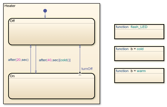
On 상태와 Off 상태 간의 천이는 지정된 시간 이후에 동작하도록 after 연산자가 사용됩니다. 예를 들어, after(20,sec)는 20초 후에 On에서 Off로의 천이를 트리거합니다. 천이 레이블 after(40,sec)[cold()]는 함수 cold가 40초 후에 true를 반환할 경우 Off에서 On으로의 천이를 트리거합니다.
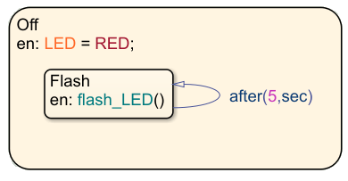
Off 상태는 상태 LED를 제어하는 자가 루프 천이가 있는 Flash라는 하위 상태를 사용합니다. 천이 레이블 after(5,sec)는 하위 상태의 entry 동작을 트리거하고 LED가 5초마다 깜빡이도록 합니다.
온도 신호 처리
Boiler Plant Model 서브시스템은 난방 또는 냉방 기간 중 보일러의 온도 반응을 시뮬레이션합니다. 서브시스템은 Bang-Bang Controller 차트의 출력에 따라 이전 보일러 온도에 대해 난방의 경우 +1을 더하며 냉방의 경우 –0.1을 뺍니다. 그런 다음, 차트는 결과를 Digital Thermometer 서브시스템으로 전달합니다.
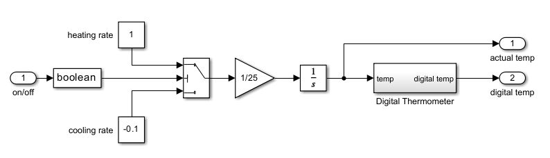
Digital Thermometer 서브시스템에서 온도 신호는 온도 측정값을 디지털 제어 값으로 변환하는 세 단계를 거칩니다.
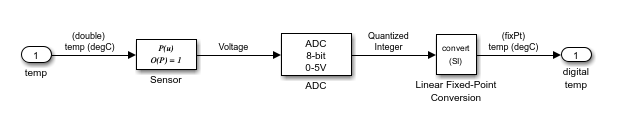
온도 신호는 원시 온도 측정값을 디지털 제어 값으로 변환하는 세 단계의 순차적 변환 과정을 거칩니다.
Sensor 블록은 선형 변환을 사용하여 보일러 온도를 아날로그 전압으로 변환하며, 그 결과 전압은 온도에 비례합니다.
Analog-to-Digital Converter 블록은 아날로그 전압을 이산 8비트 값으로 변환합니다. 시스템은 변환 인자로 전압을 곱한 다음 그 결과를 최근접 정수로 반올림하고 클램핑하여 8비트 범위 내에서 유지합니다. 출력값은 양자화된 정수입니다.
Linear Fixed-Point Conversion 블록은 이 8비트 정수를 최종 온도 값으로 처리합니다. 이 블록은 보정된 기울기와 바이어스 오프셋을 적용하여 디지털 온도 측정값을 생성합니다. 이는 8비트 환경과의 호환성을 유지하면서 측정 정확도를 보장합니다.
이 시스템은 8비트 파라미터 내에서 작동합니다. 입력 범위는 0~255, 해상도는 1/256 전체 스케일이며, 모든 계산은 고정소수점 연산방식으로 수행됩니다. 이 순서는 전체 제어 시스템에서 센서 입력값부터 최종 제어 출력값까지 일관된 온도 표현을 보장합니다.
그런 다음 Bang-Bang Controller 차트는 이 디지털 코딩된 온도를 받아 부호 없는 8비트 고정소수점 데이터로 해석합니다. 차트는 8비트 환경에서 온도 데이터를 처리합니다.
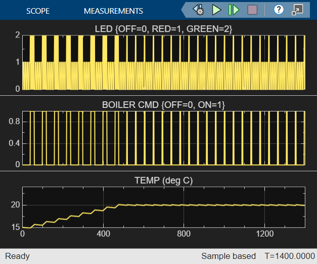
시뮬레이션 결과
시뮬레이션 결과, 보일러는 450초(7.5분) 후에 20°C에 도달합니다. 그런 다음, 뱅뱅 제어기는 남은 런타임 내내 이 목표 온도를 유지합니다.
참고 항목
after | every | Data Type Conversion (Simulink)