Specify Parameter Configuration for Structure or Bus Parameters
About This Example Model
This example describes how to generate tests that constrain the values for the
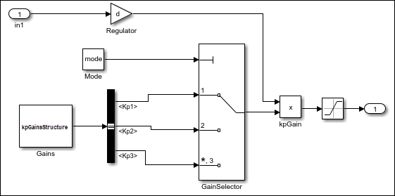
structures and bus signals in a model. Suppose that your model includes a variable
called kpGainsStructure, which is a structure in the MATLAB® workspace. The model uses a Bus Selector block to separate the
structure fields into individual bus signals. You can constrain the values of the
structure or the values of the bus signals to ensure that they stay within the
specified range during simulation.
This example describes how to create and analyze a simple Simulink® model, then use Simulink
Design Verifier™ to generate test cases for the model. The model contains an input
signal In1 whose value is set between -1 to 1.
kpGainsStructure is a structure that contains three fields,
Kp1, Kp2, and Kp3, and
outputs them to a Bus Selector block that separates the fields into individual bus
signals. The block called Mode has a constant value parameter, which is set to
mode determines the three bus signals as an input to the
kpGain block.
The value of In1 is multiplied by d, then
multiplied by the selected bus signal. The result passes to a Saturation block whose
limit is defined between -0.5 to 0.5.
Based on the mode value, Simulink selects one of the three kpGainsStructure fields
and specifies the constraints. The input signal to the Saturation
block must be below the lower limit or fall above the upper limit to satisfy the
decision objective of the Saturation block. Simulink
Design Verifier then tunes these parameters to achieve this limit. The following
workflow guides you through the process of completing this example.
Preload Workspace Variable for Structure Parameter
Preload the value of the MATLAB workspace variable kpGainsStructure. The structure
contains the fields Kp1, Kp2, and
Kp3.
On the Modeling tab, select Model Settings > Model Properties.
Click the Callbacks tab.
Click PreLoadFcn, then load the
Kp1,Kp2, andKp3fields ofmyStruct:load('struct_param.mat'); myStruct.Kp1 = 15; myStruct.Kp2 = -5; myStruct.Kp3 = -5; gainsParam = Simulink.Parameter(myStruct); mode = 1; d = Simulink.Parameter(0.012);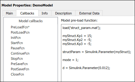
Click OK to close the Model Properties dialog box and save the model.
Because the structure parameter is called by the Constant block, you need to define the output of the Constant block as a bus. Follow these steps:
Double-click the Gains block to open Block Parameters dialog box.
Under Signal Attributes, select Output data type as
Bus:BusO.Click OK.
Define Parameter Constraint Values
There are two ways to constrain the values of structure or bus signals in the Configuration Parameter window: by using the parameter table or the parameter configuration file.
Parameter Table
Parameter configuration file
Define Parameter Constraint Values Using Parameter Table
When possible, parameter table automatically generates constraint values for each parameter, depending on the data type and location of the parameter in the model. For more information, see Use Parameter Table to Find Constraints.
Follow these steps to generate the constraint value for each parameter:
On the Apps tab, under Model Verification, Validation, and Test, click Design Verifier.
On the Design Verifier tab, click Test Generation Settings.
In Configuration Parameters dialog box, select Design Verifier > Parameters and Variants.
Select Use parameter table.
Click Find parameters.
The parameter table populates with the parameters from your model.
In the parameter table, in the Constraint column,
{1,2,3}formode[-0.01 0.15]ford
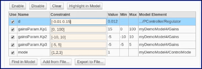
Click OK.
Define Constraint Values Using Parameter Configuration File
This is an alternative approach that you can use to define the values of constraints instead of using the Parameter Table. The Simulink Design Verifier software provides a template that you can make a copy and edit it. For more information, see Template Parameter Configuration File in Set Parameters Using Parameter Configuration File. By default, the path to the parameter configuration file is:
matlabroot/toolbox/sldv/sldv_params_template.m
To associate the parameter configuration file with your model before analyzing the model, in the Configuration Parameters dialog box, on the Design Verifier > Parameters and Variants pane, ensure that Use parameter table is cleared and enter the file name of the configuration file in the Parameter configuration file field.
Follow these steps to define the constraint values in Parameter configuration file:
In
sldv_params_template.m, enter:function params = params_config params.mode = {1, 2, 3}; params.d = [-.001 0.15]; params.gainsParam.Kp1 = Sldv.Interval(0, 50); params.gainsParam.Kp2 = Sldv.Interval(-10, 10); params.gainsParam.Kp3 = [-5, 5];Save the file with the name
params_config.m.Open the model
DemoModel.On the Apps pane, under Model Verification, Validation, and Test, click Design Verifier.
On the Design Verifier tab, click Test Generation Settings.
In Configuration Parameters dialog box, select Design Verifier > Parameters and Variants.
Click Browse, then select
params_config.mparameter configuration file created saved in step 2.
Analyze Example Model
Analyze the model with the parameter constraints enabled and generate the analysis report:
On the Design Verifier tab, in the Mode section, select Test Generation. Click Generate Tests.
Simulink Design Verifier analyzes your model to generate test cases.
When the software completes its analysis, in the Simulink Design Verifier Results Summary window, next to Detailed analysis report, select HTML.
The software displays an HTML report named
DemoModel.html.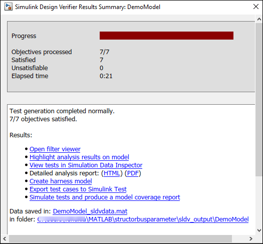
In the table of contents of the Simulink Design Verifier report, click Test Cases.
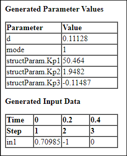
Click Test Case 1 to display the subsection for that test case.
Test Case 1 shows that Simulink Design Verifier tuned all the parameters in such a way that all the inputs coming from the In1 input signal, the Gain block and the mode variable will either fall below -0.5 or above 0.5. While generating test cases, all the constraints satisfy the objectives.
Similarly, the parameters for Test Case 2 and Test Case 3 are tuned and satisfy the objectives.