Specify Queue Properties for Message Interface
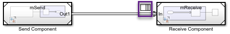
This topic explains how to specify queue properties for a message receive interface when you model message-based communication with Simulink® between software components that run in different applications. In message-based communication, a send component sends messages, and a receive component accepts messages based on the logic it represents. For more information about creating message send and receive interfaces, see Establish Message Send and Receive Interfaces Between Software Components.
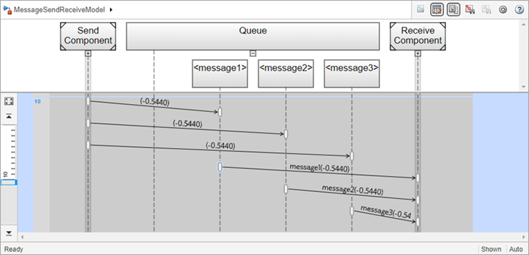
In your model with message-based communication, a queue stores and sorts messages between
send and receive components. If you do not specify queue properties manually, a LIFO
overwriting queue of capacity 1 is automatically inserted between send and
receive components. For more information on message queue configurations, see Use a Queue Block to Manage Messages.
The topic shows you how to customize queue properties for your message receive interface and summarizes their use in architecture and AUTOSAR applications.
Specify Queue Properties
Based on your application, specify queue properties for one of these three cases:
Specify message queue properties for your composition. A composition represents components and their integration. For more information, see Simulink Messages Overview.
Specify message queue properties for individual components in your model.
Specify message queue properties for both individual components and your composition.
Customize Message Queue Properties for Compositions
You can customize queue properties for your composition by manually adding a Queue block from the Simulink Messages & Events library, or blocks from the SimEvents® library.
In this example, a Queue block is manually placed to configure message queue properties when the receive interface is modeled using an Inport block and a Receive block. In this case, use Queue block parameters to specify the queue capacity, message sorting policy (FIFO or LIFO queue), and message overwriting policy.

Customize Message Queue Properties for Individual Components
You can specify queue properties for the message receive interface of an individual component using an In Bus Element block. These properties are then used by AUTOSAR to help generate target specific code for components. For more information, see Configure AUTOSAR Queued Sender-Receiver Communication (AUTOSAR Blockset).
Open the In Bus Element block. Select the bus element and specify its data mode using the Data mode parameter.

Select the message icon to configure queue properties for the selected message element.

Clear the Use default queue attributes check box to specify queue attributes for the message element.

Customize Message Queue Properties for Components and Compositions
In this scenario, you combine components with queue receive interface specifications and explicit queues. When you use both of these queue specifications, the explicit queue configuration will overwrite other queue specifications.

If you choose both configurations at the same time, you will receive this warning, which indicates that the configuration of the Queue block overwrites other queue configurations.

Queue Expansion
If you use an automatically inserted Queue block or manually place a Queue block between send and receive components, for all of the queue specification methods, the queue expands to multiple queues to provide storage for each virtual bus message element. In this case, all of the queues have the same configuration and capacity as the original queue. For an example, see Use Virtual Buses with Message Elements for Component Communication.
If you use an In Bus Element block to model the receive interface, you can use multiple In Bus Element blocks to insert a different message queue for each received message element. The queue icon displays queue specifications for each message element.

Virtual Buses with Message Elements in Architecture Models
You can model message-based communication between software components by first designing your system from the architecture level using System Composer™. The architecture models in System Composer support Simulink models with message input and output as component behaviors. Designing message interfaces from the architecture level requires a System Composer license.
This illustration shows the design of the architecture with send and receive
components.. The Simulink models used in the example above, mSend and
mReceive, are attached to these components as component behaviors. When
you compile the model, a LIFO queue of capacity 1 is automatically
inserted to the architecture model for simulation.
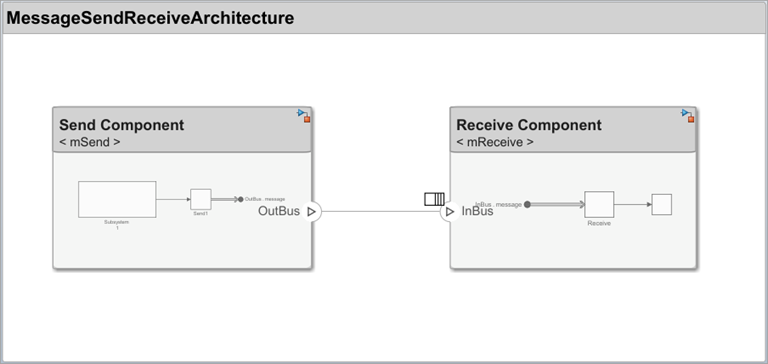
You can also use the In Bus Element block to manually specify queue properties for the receive interface behavior of your architecture component. After you update your model, you can point to the queue icon to view the queue configurations for each bus element in the component behavior.
![]()
See Also
Topics
- Use Virtual Buses with Message Elements for Component Communication
- Generate C++ Messages to Communicate Data Between Simulink and an Operating System or Middleware (Embedded Coder)
- Establish Message Send and Receive Interfaces Between Software Components
- Model an Ethernet Communication Network with CSMA/CD Protocol
- Simulink Messages Overview