Main Content

LSM6DSM IMU Sensor

Measure linear acceleration, angular rate, and temperature from LSM6DSM sensor

Since R2022b

Add-On Required: This feature requires the Simulink Support Package for Raspberry Pi Hardware add-on.

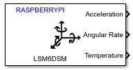
  • block icon for LSM6DSM IMU Sensor

Libraries:
Simulink Support Package for Raspberry Pi Hardware / Sensors / IMU Sensors

Description

The LSM6DSM IMU Sensor block measures linear acceleration and angular rate along the X, Y, and Z axis using the LSM6DSM Inertial Measurement Unit (IMU) sensor interfaced with the Raspberry Pi® hardware. This 6-Degree of Freedom (DoF) IMU sensor comprises of an accelerometer and gyroscope used to measure linear acceleration and angular rate, respectively. The block also measures the temperature from the embedded temperature sensor in LSM6DSM Sensor.

You can also use the composite filter option in the block for the accelerometer values, and use the high pass and low pass filter options for gyroscope values.

Ports

Output

expand all

You can select the active sensor(s) to measure angular velocity, acceleration, temperature, or a combination of these measurements.

The block outputs acceleration as a 1-by-3 vector. Each value represents the measurement of acceleration in m/s^2 along the X, Y, and Z axes.

Dependencies

This output port appears only if you select the Acceleration (m/s2) parameter.

Data Types: double

The block outputs angular velocity as a 1-by-3 vector. Each value represents the measurement of angular velocity in radians per second (rad/s) along the X, Y, and Z axes.

Dependencies

This output port appears only if you select the Angular Velocity (rad/s) parameter.

Data Types: double

Temperature (in ℃) measured by LSM6DSM sensor connected to Raspberry Pi board.

Dependencies

This output port appears only if you select the Temperature (℃) parameter.

Data Types: double

Status of acceleration, angular velocity and temperature measurements, specified as a 1-by-3 vector. 0 indicates that the data read is new, 1 indicates that the data read is not new, and -1 indicates that the corresponding output is not selected.

Dependencies

This output port appears only if you select the Status parameter.

Data Types: int8

Parameters

expand all

Main

Specify the module on the board that you are using for I2C communication.

The peripheral addresses to communicate with the accelerometer and gyroscope peripherals on the LSM6DSM sensor are decided by the state of the SDO/SA0 pin on the hardware board. This table provides the peripheral addresses corresponding to the pin and their state.

Pin NamePin StatePeripheral Address
SDO/SA000x6A
10x6B

Select this parameter to set Acceleration as one of the output ports.

Select this parameter to set Angular Velocity as one of the output ports.

Select this parameter to set Temperature as one of the output ports.

Select this parameter to set Status as one of the output ports.

Specify how often this block reads the data from the LSM6DSM sensor. When you set this parameter to -1, Simulink determines the best sample time for the block based on the block context within the model.

Advanced

Accelerometer

Select the full scale for measuring linear acceleration (the range of acceleration that the sensor needs to measure).

Select the output data rate at which accelerometer data is sampled, which also determines the bandwidth.

Select the required bandwidth of the low-pass digital filter.

Select the type of composite filter used in the filtering chain for reading accelerometer values.

Select the required bandwidth of the high pass filter in the composite filter used in the filtering chain.

Dependencies

This parameter appears only if you select High pass filter in the Select composite filter parameter.

Select the required bandwidth of the low pass filter in the composite filter used in the filtering chain.

Dependencies

This parameter appears only if you select Low pass filter in the Select composite filter parameter.

Gyroscope

Select the full scale for measuring angular velocity (the range of angular velocity that the sensor needs to measure).

Select the output data rate at which gyroscope data is sampled, which also determines the bandwidth.

Enable the high pass filter for reading gyroscope values.

Select the required bandwidth of the high pass filter for reading gyroscope values.

Dependencies

This parameter appears only if you select the Enable high pass filter parameter.

Enable the low pass filter for reading gyroscope values.

Select the required bandwidth mode of the low pass filter for reading gyroscope values.

Dependencies

This parameter appears only if you select the Enable low pass filter parameter.

Version History

Introduced in R2022b

Go to top of page