Simulink Engine Interaction with C S-Functions
You can examine how the Simulink® engine interacts with S-functions from two perspectives:
Process perspective, i.e., at which points in a simulation the engine invokes the S-function.
Data perspective, i.e., how the engine and the S-function exchange information during a simulation.
Process View
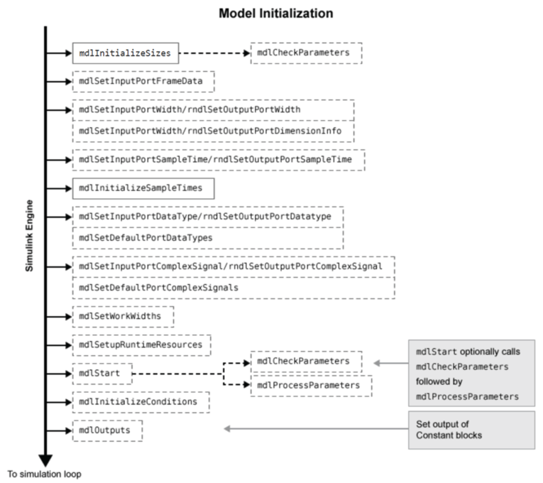
The following figures show the order in which the Simulink engine invokes the callback methods in an S-function. Solid rectangles indicate callbacks that always occur during model initialization or at every time step. Dotted rectangles indicate callbacks that may occur during initialization and/or at some or all time steps during the simulation loop. See the documentation for each callback method to determine the exact circumstances under which the engine invokes the callback.
Note
The process view diagram represents the execution of S-functions that contain continuous and discrete states, enable zero-crossing detection, and reside in a model that uses a variable-step solver. Different solvers omit certain steps in the diagram. For a better understanding of how the Simulink engine executes your particular S-function, run the model containing the S-function using the Simulink debugger.
In the following model initialization loop, the Simulink engine configures the S-function for an upcoming simulation. The engine always
makes the required calls to mdlInitializeSizes and
mdlInitializeSampleTime to set up the fundamental attributes of the
S-function, including input and output ports, S-function dialog parameters, work vectors,
sample times, etc.
The engine calls additional methods, as needed, to complete the S-function
initialization. For example, if the S-function uses work vectors, the engine calls
mdlSetWorkWidths. Also, if the mdlInitializeSizes
method deferred setting up input and output port attributes, the engine calls any methods
necessary to complete the port initialization, such as
mdlSetInputPortWidth, during signal propagation. The
mdlStart method calls the mdlCheckParameters and
mdlProcessParameters methods if the S-function uses dialog
parameters.
Note
The mdlInitializeSizes callback method also runs when you enter the
name of a compiled S-function into the S-Function Block Parameters dialog box.
After initialization, the Simulink engine executes the following simulation loop. If the simulation loop is
interrupted, either manually or when an error occurs, the engine jumps directly to the
mdlTerminate method. If the simulation was
manually halted, the engine first completes the current time step before invoking
mdlTerminate.

If your model contains multiple S-Function blocks at a given level of model hierarchy,
the engine invokes a particular method for every S-function before proceeding to the next
method. For example, the engine calls all the mdlInitializeSizes methods
before calling any mdlInitializeSampleTimes methods. The engine uses the
block sorted order to determine the order to execute the S-functions. To learn more about
how the engine determines the block execution order, see Control and Display Execution Order.
Calling Structure for Code Generation
If you use the Simulink
Coder™ product to generate code for a model containing S-functions, the Simulink engine does not execute the entire calling sequence outlined above.
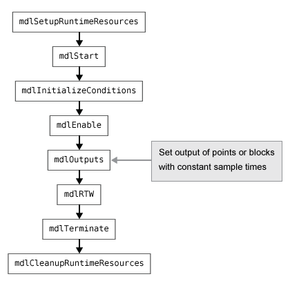
Initialization proceeds as outlined above until the engine reaches the
mdlStart method. The engine then calls the S-function methods shown
in the following figure, where the mdlRTW method is unique to the
Simulink
Coder product.
If the S-function resides in a conditionally executed subsystem, it is possible for
the generated code to interleave calls to mdlInitializeConditions and
mdlStart. Consider the following Simulink model.
The model contains two nonvirtual
subsystems, the conditionally executed enabled subsystem named Reset and the
atomic subsystem named Atomic. Each subsystem contains an S-Function block that calls the
S-function dsfunc.c, which models a discrete state-space system with
two states. The enabled subsystem Reset resets the state values when the subsystem is
enabled, and the output values when the subsystem is disabled.
Using the generic real-time (GRT) target, the generated code for the model-wide
Start function calls the Start functions of the
two subsystems before calling the model-wide MdlInitialize function, as
shown in the following code:
void MdlStart(void)
{
  /* snip */

  /* Start for enabled SubSystem: '<Root>/Reset' */
  sfcndemo_enablesub_Reset_Start();

  /* end of Start for SubSystem: '<Root>/Reset' */

  /* Start for atomic SubSystem: '<Root>/Atomic' */
  sfcndemo_enablesub_Atomic_Start();

  /* end of Start for SubSystem: '<Root>/Atomic' */

MdlInitialize();
The Start function for the enabled subsystem calls the subsystem's
InitializeConditions function:
void sfcndemo_enablesub_Reset_Start(void)
{
   sfcndemo_enablesub_Reset_Init();
   /* snip */
}
The MdlInitialize function, called in MdlStart,
contains a call to the InitializeConditions function for the atomic
subsystem:
void MdlInitialize(void)
{
   /* InitializeConditions for atomic SubSystem:
        '<Root>/Atomic' */

   sfcndemo_enablesub_Atomic_Init();
}
Therefore, the model-wide Start function interleaves calls to the
Start and InitializeConditions functions for the
two subsystems and the S-functions they contain.
For more information about the Simulink Coder product and how it interacts with S-functions, see S-Functions and Code Generation (Simulink Coder).
Alternate Calling Structure for External Mode
When you are running a Simulink model in external mode, the calling sequence for S-function routines changes as shown in the following figure.
The engine calls mdlRTW once when it enters external mode and again
each time a parameter changes or when you click Update Model on the
Modeling tab.
Note
See External Mode Communication (Simulink Coder) for the requirements for running in external mode.
Data View
S-function blocks have input and output signals, parameters, and internal states, plus other general work areas. In general, block inputs and outputs are written to, and read from, a block I/O vector. Inputs can also come from
External inputs via the root Inport blocks
Ground if the input signal is unconnected or grounded
Block outputs can also go to the external outputs via the root Outport blocks. In addition to input and output signals, S-functions can have
Continuous states
Discrete states
Other working areas such as real, integer, or pointer work vectors
You can parameterize S-function blocks by passing parameters to them using the S-Function Block Parameters dialog box.
The following figure shows the general mapping between these various types of data.
An S-function's mdlInitializeSizes routine sets the sizes of
the various signals and vectors. S-function methods called during the simulation loop can
determine the sizes and values of the signals.
An S-function method can access input signals in two ways:
Via pointers
Using contiguous inputs
Accessing Signals Using Pointers
During the simulation loop, access the input signals using
InputRealPtrsType uPtrs =
  ssGetInputPortRealSignalPtrs(S,portIndex)
This returns an array of pointers for the input port with index
portIndex, where portIndex starts
at 0. There is one array of pointers for each input port. To access an element of this
array you must use
*uPtrs[element]
The following figure describes how to access the input signals of an S-function with two inputs.
As shown in the previous figure, the input array pointers can point at noncontiguous places in memory.
You can retrieve the output signal by using this code.
real_T *y = ssGetOutputPortSignal(S,outputPortIndex);
Note
Starting in R2026a, S-Function blocks support only contiguous inputs. It is
recommended to use the contiguous input functions ssGetInputPortSignal and ssGetInputPortRealSignal instead of
ssGetInputPortSignalPtrs and
ssGetInputPortRealSignalPtrs, respectively. The contiguous input
functions provide faster access and improved performance by removing the need for double
pointer to access signals.
Accessing Contiguous Input Signals
An S-function's mdlInitializeSizes method can specify that the
elements of its input signals must occupy contiguous areas of memory, using ssSetInputPortRequiredContiguous. If the inputs are contiguous, other
methods can use ssGetInputPortSignal to access the
inputs.
Accessing Input Signals of Individual Ports
This section describes how to access all input signals of a particular port and write them to the output port. The preceding figure shows that the input array of pointers can point to noncontiguous entries in the block I/O vector. The output signals of a particular port form a contiguous vector. Therefore, the correct way to access input elements and write them to the output elements (assuming the input and output ports have equal widths) is to use this code.
int_T element;
int_T portWidth = ssGetInputPortWidth(S,inputPortIndex);
InputRealPtrsType uPtrs = ssGetInputPortRealSignalPtrs(S,inputPortIndex);
real_T *y = ssGetOutputPortSignal(S,outputPortIdx);

for (element=0; element<portWidth; element++) {
  y[element] = *uPtrs[element];
}
A common mistake is to try to access the input signals via pointer arithmetic. For example, if you were to place
real_T *u = *uPtrs; /* Incorrect */
just below the initialization of uPtrs and replace the inner part
of the above loop with
*y++ = *u++; /* Incorrect */
the code compiles, but the MEX file might crash the Simulink software. This is because it is possible to access invalid memory (which depends on how you build your model). When accessing the input signals incorrectly, a crash occurs when the signals entering your S-function block are not contiguous. Noncontiguous signal data occurs when signals pass through virtual connection blocks such as the Mux or Selector blocks.
To verify that your S-function correctly accesses wide input signals, pass a replicated signal to each input port of your S-function. To do this, create a Mux block with the number of input ports equal to the width of the desired signal entering your S-function. Then, connect the driving source to each S-function input port, as shown in the following figure. Finally, run your S-function using this input signal to verify that it does not crash and produces expected results.
See Also
Level-2 MATLAB S-Function | S-Function Builder | S-Function | MATLAB Function