Modelling ADC Impairments in SerDes Receiver
This example shows how to model the effects of ADC Impairments, including offset error, gain error, and differences between interleaved ADCs on the performance of a SerDes Receiver. This example is based on the Architectural 112G PAM4 ADC Based SerDes Example, which explains the model as a whole, its purpose, and theory of operation in more detail.
Replace the ADC Model
Open the model ArchitecturalADCBasedSerDes.slx and navigate into Rx/ADC_EQ/. Inside the ADC_EQ subsystem, place a MATLAB System block.

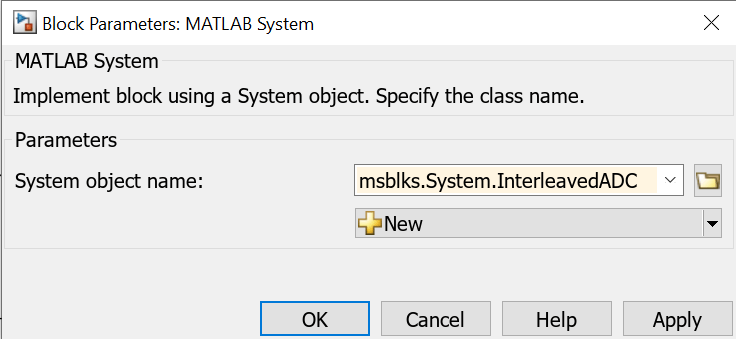
Open the mask of that MATLAB System block and set System object name to msblks.System.InterleavedADC. Applying this change will cause the MATLAB System block to take on the attributes of the Mixed-Signal Blockset Interleaved ADC, which models several impairments.

Replace the old Time Interleaved ADC block with the new MATLAB System (Interleaved ADC) block. Set the parameters of the new Interleaved ADC block to achieve the impaired behavior. The Mixed-Signal Blockset Interleaved ADC supports Offset error, Gain error, and Conversion delay impairments on a per-core basis. The parameters Number of bits and Input range may similarly be set on a per-core basis. When setting parameters on a per-core basis, such as Offset error and Gain error below, the number of elements of their values should match the Number of ADCs.
Configuration:
Number of bits should be
8Input range should be
[-0.2, 0.2]Linearly interpolate analog input to find sampled value should be checked because the start clock is sinusoidal
Number of ADCs should be
timeInterleaveDepth, which is4by defaultMatch output to input scale should be checked
Output data type should be
doubleConvert the output to scalar should be unchecked
Sample interval (s) should be
SampleInterval
Impairments:
Offset error should be
[1, 5, -3, -4]to set a different offset error impairment for each ADC coreGain error should be
[-7, 1, -6, 5]to set a different gain error impairment for each ADC coreConversion delay (seconds) impairment to
SymbolTime * (timeInterleaveDepth - 1)
Leave the other parameters at their default values and apply the changes.

Simulate the Model
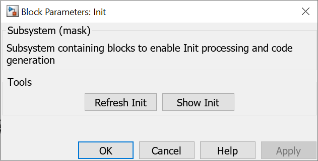
Before starting the model, generate the statistical simulation code. Open the mask of ADCBasedSerDes_ImpairedADC/Rx/Init and click the "Refresh Init" button.

Now that new init code has been generated, run the simulation in Simulink.

Generate IBIS-AMI Model
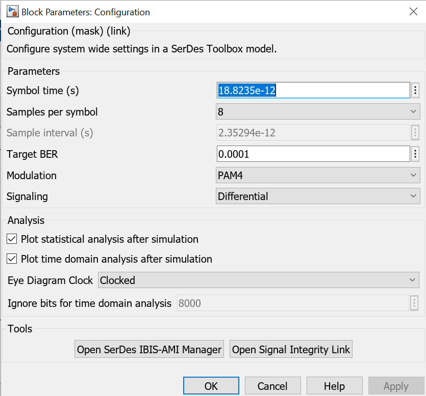
The Mixed-Signal Blockset Interleaved ADC supports IBIS-AMI model generation through the SerDes Toolbox Configuration block. Open the SerDes IBIS-AMI Manager from the mask of the Configuration block and click export to create an IBIS-AMI model.

