Log CAN Bus Data on Raspberry Pi
R2026bThis example shows how to use Raspberry Pi® Blockset to monitor a controller area network (CAN) bus, perform basic CAN conversions, and log CAN FD data in a measurable data format (MDF) file. This example also showcases the interoperability between a model deployed in Simulink® and a Python® program running simultaneously on Raspberry Pi hardware.
The automotive industry extensively uses CAN due to its robustness, real-time capabilities, and ability to efficiently transfer data at higher rates and larger payloads. This example uses the latest MDF4 format to store the CAN FD data. This format enables you to analyze and interpret the data offline without any constraints of real-time processing. The format enables efficient data compression and provides support for more complex data structures.
Simulink Models and Supported Files
Implementing this example requires you to successfully deploy these Simulink models and run a Python script on your Raspberry Pi board.
raspberrypi_CAN_traffic_generator.slx— Simulink model that generates CAN FD data to transmit over the CAN bus.raspberrypi_CAN_MDF_logging.slx— Simulink model to receive the CAN FD data and send it to the Python program using interprocess communication.raspberrypi_can_fd_bus_logger.py— Python script to receive CAN FD messages with payload sizes up to 64 bytes from the Simulink model through interprocess communication and logs the data, including BRS, ESI, and DLC information, to an MDF4 file on the Raspberry Pi.raspberrypi_classical_can_bus_logger.py— Python script to receive classical CAN messages with payload sizes up to 8 bytes from the Simulink model through interprocess communication and logs the data to an MDF4 file on the Raspberry Pi.raspberrypi_classical_can_fd_bus_logger.py— Python script to receive CAN FD messages with payload sizes up to 64 bytes from the Simulink model through interprocess communication and logs the data, including bit rate switching, error status indicator, and data length code information, to an MDF4 file on the Raspberry Pi.
Convert This Example for Classical CAN
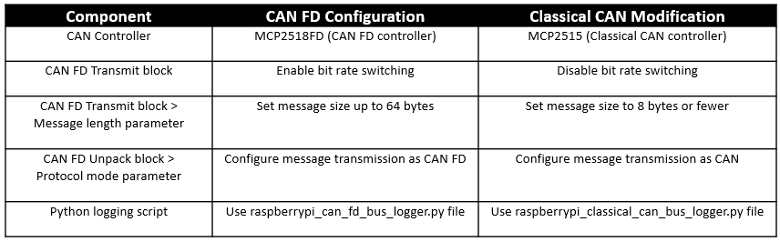
This example is preconfigured for CAN FD communication. To use this example for classical CAN, modify these components as follows.
Example Workflow
This diagram explains the relationship and dependencies between the components and processes used in the example such as the Raspberry Pi board, CAN bus, interprocess communication, and MDF logging.
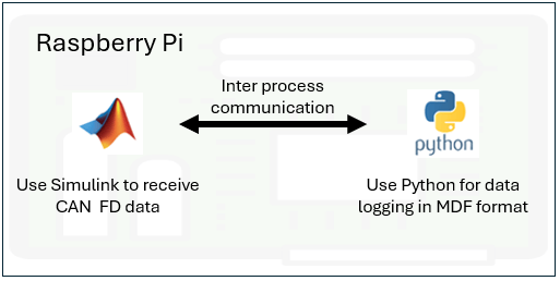
Use Simulink to create and deploy a model on the Raspberry Pi hardware to receive CAN FD data. Run a Python script on the Raspberry Pi hardware to log the received CAN FD data in the MDF format. Transfer the MDF file from Raspberry Pi to Simulink for further analysis. Because the various components in the system interact in real time, you can record the relevant data in an MDF file for future analysis or troubleshooting purposes.
Installing Third-Party Libraries and Packages
When installing Raspberry Pi Blockset, make sure to set up these third-party libraries and packages that are included in the interprocess communication bundle.
nng
ninja_build
For more information, see Install Interprocess Communication Bundle.
Hardware Requirements
You need these components to set up CAN bus communication using Raspberry Pi:
Raspberry Pi board
Any MCP2518FD-based dual-channel CAN FD HAT. This example uses a Waveshare® 2-Channel CAN FD HAT.
Jumper wires
CAN bus cables
Hardware Connections
Connect both the CANH lines between the CAN shield and CAN bus. Similarly, connect both the CANL lines between the CAN shield and CAN bus.
Configuring CAN Modules
For this example, use these pointers while configuring the CAN modules:
This example uses physical CAN hardware to make sure that communication and data logging are accurate. For setting up a virtual CAN interface, see Setup Virtual CAN Interface.
This example uses dual-shield CAN modules, can0 and can1, where can1 is used for transmission of CAN FD data and can0 is used for reception of CAN FD data.
To initiate CAN communication on your Raspberry Pi, make sure to enable SPI communication on your board. After you enable SPI communication, individually configure the can0 and can1 modules. For more information, see Enable and Configure Raspberry Pi for SPI and CAN FD Communication Using Waveshare 2-CH CAN FD HAT.
The loopback connection of the CANH and CANL lines creates a direct communication between the CAN shield and the CAN bus.
After you configure the CAN modules, make sure to reboot your Raspberry Pi board for the changes to apply.
Configure raspberrypi_CAN_traffic_generator Simulink Model
Use the raspberrypi_CAN_traffic_generator Simulink Model to transmit CAN FD messages over the MCP2518FD CAN controller bus connected to your Raspberry Pi board.
Open the raspberrypi_CAN_traffic_generator Simulink model.
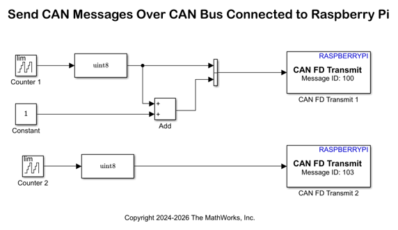
This model uses two CAN FD Transmit blocks, with the CAN FD Transmit 1 block using data of message ID 100 and the CAN FD Transmit 2 block using 103. Input raw data to the two CAN FD Transmit blocks as a two-element vector. The can1 module transmits CAN FD data.
Configure these parameters in the Block Parameters dialog box of the CAN FD Transmit 1 block.
Set CAN interface to
can1.Set Data is input as to
Raw data.Select Enable bit rate switching and Wait until data sent parameters.
Set Timeout in seconds to
1.Set Message ID to
100.Set Message length to
2.
Configure these parameters in the Block Parameters dialog box of the CAN FD Transmit 2 block.
Set CAN interface to
can1.Set Data is input as to
Raw data.Select Enable bit rate switching and Wait until data sent parameters.
Set Timeout in seconds to
1.Set Message ID to
103.Set Message length to
1.
For more information, see CAN FD Transmit block
The sample time of Counter 1 is 0.5 seconds while that of Counter 2 is 0.1 seconds. Based on these values, the CAN FD Transmit 1 block transmits 2 counter values per second and CAN FD Transmit 2 block transmits 10 counter values per second. You can observe these value while logging the CAN FD data in MATLAB®. For more information on the Counter block, see Counter Limited (Simulink).
Configure these parameters in the Configuration Parameters dialog box > Target hardware resources > CAN parameters of the raspberrypi_CAN_traffic_generator Simulink Model.
Set Interface configuration to
Specify via Simulink.Set Number of CAN interfaces to
1.Set Name to
can1.Set Type to
Real.Set CAN protocol to
CAN FD.
For more information on configuring CAN modules, see CAN.
Configure raspberrypi_CAN_MDF_logging Simulink Model
Use the raspberrypi_CAN_MDF_logging Simulink model to receive the CAN raw data on message IDs 100 and 103 and log the data in an MDF file. Observe that the Simulink model utilizes a single CAN FD Receive block to listen to all messages on the bus in the CAN Msg mode. This behavior is due to the broadcasting nature of the CAN bus and the ability to filter and process messages based on their identifiers.
Open the raspberrypi_CAN_MDF_logging Simulink model.
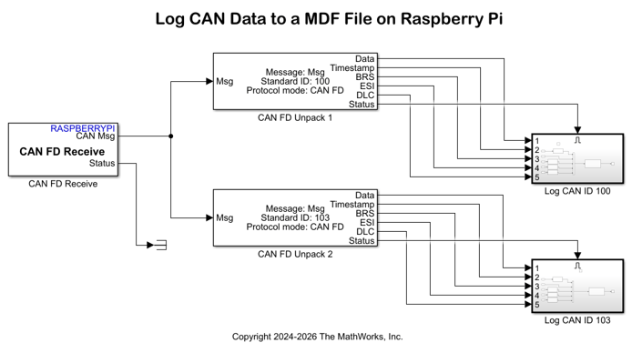
The model uses the can0 module to receive CAN FD data. The model also uses the CAN Unpack blocks to unpack the CAN FD messages from the CAN bus. The CAN FD Unpack (Embedded Coder) block unpacks individual signals from CAN message ID 100, while the CAN FD Unpack (Embedded Coder) block unpacks signals from CAN message ID 103. For this example, retrieve data, timestamp, and status signals from the CAN FD Unpack blocks in the model. For more information, see CAN FD Unpack (Embedded Coder).
Configure these parameters in the Block Parameters dialog box of the CAN FD Receive block.
Set CAN interface to
can0.Set Data to be output as to
CAN Msg.Set Sample time to
0.05. Make sure that the receiver sampling time is lower than the transmitter sampling time in the CAN FD Transmit blocks for theraspberrypi_CAN_traffic_generatorSimulink model.
Configure these parameters in the Block Parameters dialog box of the CAN FD Unpack (Embedded Coder) block.
Set Data to output as to
raw data.Specify
Msgin the Name parameter.Set Protocol mode to
CAN FD.Set Identifier to
100. Make sure you set the same CAN FD message ID as you configure in the Message ID parameter of the CAN FD Transmit blocks in theraspberrypi_CAN_traffic_generatorSimulink model.Set Length (bytes) to
2. Make sure you set the same CAN FD message length as you configure in the Message length parameter of the CAN FD Transmit block in theraspberrypi_CAN_traffic_generatorSimulink model.To view timestamp and status output ports, select Output timestamp and Output status.
To enable bit rate switching for CAN FD communication, select Output Bit Rate Switch (BRS).
To output the error status indicator, select Output Error Status Indicator (ESI).
To output the message data length, select Output Data Length Code (DLC).
Configure these parameters in the Block Parameters dialog box of the CAN FD Unpack (Embedded Coder) block.
Set Data to output as to
raw data.Set Identifier to
103.Set Length (bytes) to
1.To view timestamp and status output ports, select Output timestamp and Output status.
Use the Status port output from the CAN FD Unpack (Embedded Coder) blocks to trigger the Log CAN ID 100 and Log CAN ID 103 subsystems. The subsystems are triggered only when the Status port output is 1, which means that the block receives a new CAN message from the CAN bus. The subsystems also receive data and timestamp outputs from the CAN FD Unpack blocks for further processing.
Use the NNG Send blocks, one for each CAN message ID, to broadcast CAN FD data to all applications subscribing to the same uniform resource locator (URL). Configure the NNG Send blocks to filter messages by CAN message IDs.
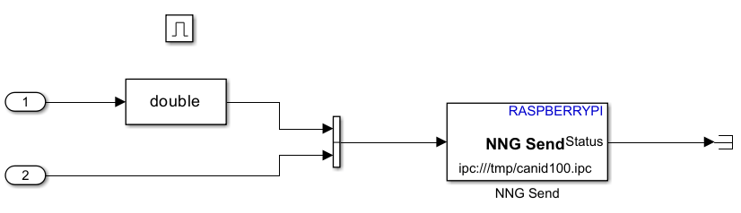
In the block parameters dialog box of the NNG Send block in the Log CAN ID 100 subsystem, set IPC name to canid100.
In the block parameters dialog box of the NNG Send block in the Log CAN ID 103 subsystem, set IPC name to canid103.
Configure the can1 module using the CAN in the same way as the can0 module.
Run and Deploy Simulink Models on Raspberry Pi
Follow these steps to deploy the raspberrypi_CAN_traffic_generator.slx and raspberrypi_CAN_MDF_logging.slx Simulink models on your Raspberry Pi. To initiate CAN communication, deploy the raspberrypi_CAN_traffic_generator.slx model on your Raspberry Pi first.
Open the
raspberrypi_CAN_traffic_generator.slxmodel.On the Hardware tab of the model, in the Deploy section, click Build, Deploy & Start.
Open the
raspberrypi_CAN_MDF_loggingmodel.On the Hardware tab of the model, in the Run on Hardware section, click Monitor & Tune.
Use the Simulation Data Inspector application to visualize the Counter Limited (Simulink) and Counter Limited (Simulink) CAN FD data that the CAN FD Unpack (Embedded Coder) blocks output on the Data port in the raspberrypi_CAN_MDF_logging model.
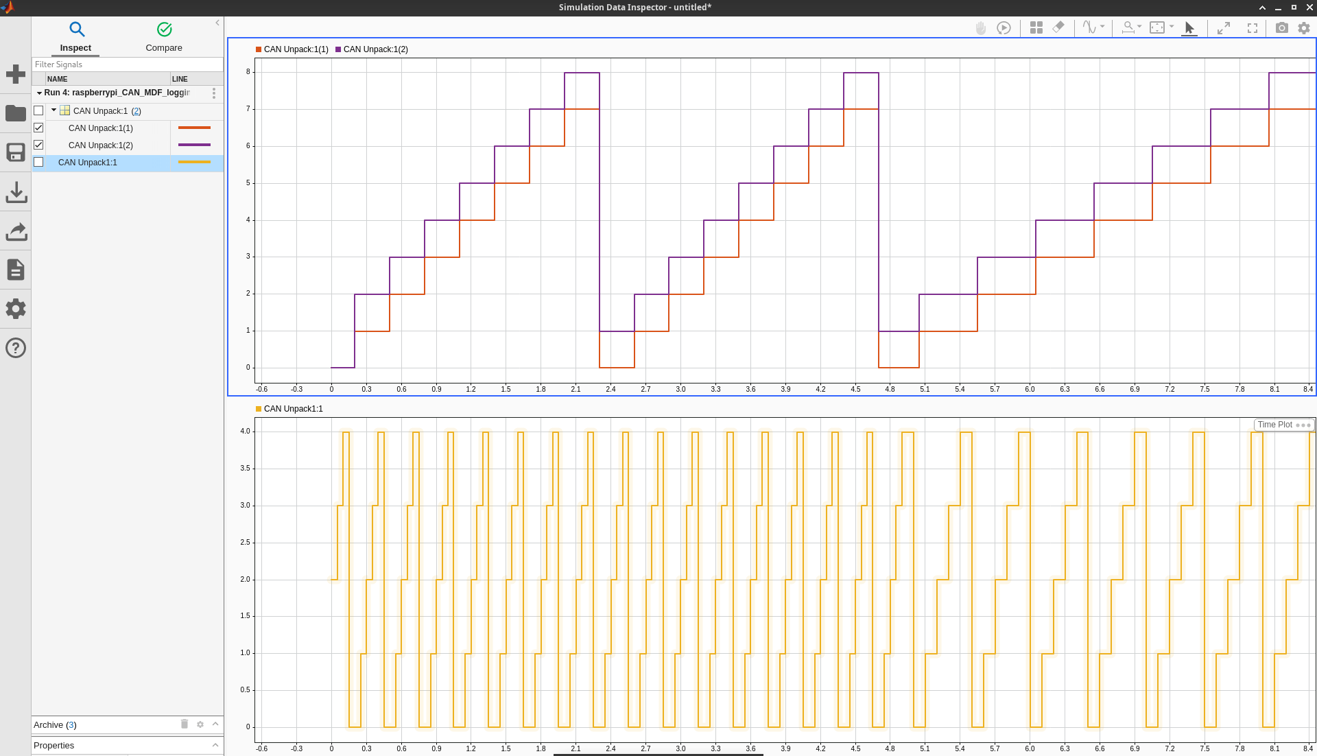
Log CAN FD Data into MDF File
Use the raspberrypi_can_fd_bus_logger.py Python script to log data into an MDF file on the Raspberry Pi hardware. You can locate this file in the current directory of the example folder. The script sets up a multi-threaded environment to listen for CAN messages on IPC channels and logs it into an MDF4 file format. It uses the ASAM MDF library to handle the data format and uses locks to maintain thread safety during data updates. In the raspberrypi_can_fd_bus_logger.py Python script, make sure to capture these points and take care to match them with specific parameters in the blocks of the Simulink models.
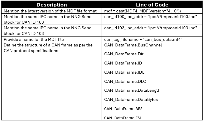
Run raspberrypi_can_fd_bus_logger.py Python Script on Raspberry Pi Terminal
When you install Raspberry Pi Blockset, MATLAB creates the virtual environment required to run a Python script on your Raspberry Pi hardware by installing the core bundle third-party libraries and packages.
In the MATLAB Command Window, execute these command to open the Raspberry Pi terminal.
r=raspberrypi('<Raspberry Pi IP address>','<Raspberry Pi username>','<Raspberry Pi password>');
r.openShell
Transfer the raspberrypi_can_fd_bus_logger.py file from the host computer to the Raspberry Pi. Simulink places this Python script in the current folder of the Raspberry Pi.
r.putFile('raspberrypi_can_fd_bus_logger.py')In the Raspberry Pi terminal, execute this command to activate a Python virtual environment of Linux®.
source /opt/mw_venv/bin/activate
Install the NNG and asammdf libraries on the Raspberry Pi.
pip3 install pynng
pip3 install asammdf
Execute the raspberrypi_can_fd_bus_logger.py script on the Raspberry Pi to capture CAN specifications for CAN messages.
python3 raspberrypi_can_fd_bus_logger.py
Let this command run on your Raspberry Pi for some time. You will receive these messages when the command is runs on your Raspberry Pi.
Starting thread for CAN Msg ID: 100
Starting thread for CAN Msg ID: 103
This script keeps running for infinity on your Raspberry Pi. Press Ctrl+C to kill the Python script. This process generates the MF4 file in the current folder of your Raspberry Pi. You can view this message on the Raspberry Pi terminal.
Preparing to save data to can_bus_data.mf4
Saved. All done!
In the MATLAB Command Window, execute this command to transfer the can_bus_data.mf4 file from the Raspberry Pi to your host computer. Observe the file in the current working directory on your MATLAB session.
r.getFile('can_bus_data.mf4')Get channel metadata from MDF file. This function returns a table of information about all channels in the can_bus_data.mf4 MDF file.
canLoggedDataInfo = mdfChannelInfo("can_bus_data.mf4")

Read all available data from the can_bus_data.mf4 MDF file and assign the output to the cell array data.
canLoggedData = mdfRead('can_bus_data.mf4')Access the first element of the canLoggedData variable.
canLoggedData{1}
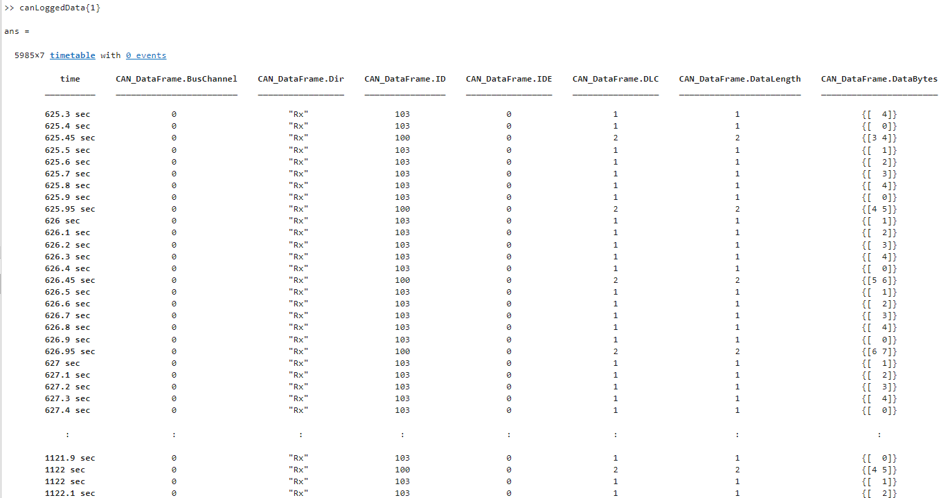
You can utilize Raspberry Pi Blockset, along with Python and interprocess communication capabilities, to efficiently analyze and process CAN FD data offline according to your requirements.
Other Things to Try
Instead of using the raspberrypi_CAN_traffic_generator.slx model to generate CAN FD data, you can use any other source to generate CAN FD data. In this case, deploy only the raspberrypi_CAN_MDF_logging.slx model on your Raspberry Pi and adjust the code in the Python script accordingly.
See Also
Enable and Configure Raspberry Pi for SPI and CAN FD Communication Using Waveshare 2-CH CAN FD HAT
Enable and Configure Raspberry Pi for SPI and CAN Communication Using MCP2515 CAN Controller
mdfRead(Vehicle Network Toolbox)mdfChannelInfo(Vehicle Network Toolbox)

