Radar Equation
Radar Equation Theory
The point target radar range equation estimates the power at the input to the receiver for a target of a given radar cross section at a specified range. In this equation, the signal model is assumed to be deterministic. The equation for the power at the input to the receiver is
where the terms in the equation are:
Pr — Received power in watts.
Pt — Peak transmit power in watts.
Gt — Transmitter gain.
Gr — Receiver gain.
λ — Radar operating frequency wavelength in meters.
σ — Target's nonfluctuating radar cross section in square meters.
L — General loss factor to account for both system and propagation loss.
Rt — Range from the transmitter to the target.
Rr — Range from the receiver to the target. If the radar is monostatic, the transmitter and receiver ranges are identical.
Sometimes the radar equation is written to include a pattern propagation factor F which takes into account the effects of wave propagation in a non-free space environment where constructive or destructive interference can occur. While the radar equation presented here does not include this term, it can be easily included in the general loss factor, L, by replacing L by L/F. Omitting this term is equivalent to setting F = 1.
The equation for the power at the input to the receiver represents the signal term in the signal-to-noise ratio (SNR). To model the noise term, assume the thermal noise in the receiver has a white noise power spectral density (PSD) given by
where k is the Boltzmann constant and T is the effective noise temperature. The receiver acts as a filter to shape the white noise PSD. Assume that the magnitude squared receiver frequency response approximates a rectangular filter with bandwidth equal to the reciprocal of the pulse duration, 1/τ. The total noise power at the output of the receiver is
where Fn is the receiver noise figure.
The product of the effective noise temperature and the receiver noise factor is referred to as the system temperature and is denoted by Ts, so that Ts = TFn .
Using the equation for the received signal power and the output noise power, the receiver output SNR is
Solving for the required peak transmit power,
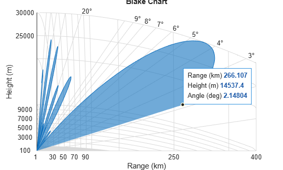
Plot Vertical Coverage Pattern Using Default Parameters
Set the frequency to 100 MHz, the antenna height to 10 m, and the free-space range to 200 km. The antenna pattern, surface roughness, antenna tilt angle, and field polarization assume their default values as specified in the AntennaPattern, SurfaceRoughness, TiltAngle, and Polarization properties.
Obtain an array of vertical coverage pattern values and angles.
freq = 100e6;
ant_height = 10;
rng_fs = 200;
[vcp,vcpangles] = radarvcd(freq,rng_fs,ant_height);
To see the vertical coverage pattern, omit the output arguments.
radarvcd(freq,rng_fs,ant_height);
Required Peak Power for a Monostatic Radar
This example shows how to calculate the required peak transmit power for a monostatic radar to detect a large target at 10 km given a probability of detection of 0.9 and a probability of false alarm of 0.0001. The radar operates at 10 GHz with a 40 dB antenna gain and a system loss of 5 dB.
Calculate SNR Given the Probability of Detection
Calculate the signal-to-noise ratio (SNR) given a probability of detection of 0.9 and a probability of false alarms of 0.0001. Use the shnidman function.
Pd  = 0.9;    % Probability of detection
Pfa = 0.0001; % Probability of false alarm
SNR = shnidman(Pd,Pfa)
SNR =
11.7627
Calculate Peak Power from SNR
Calculate the peak transmit power from SNR using the radareqpow function.
fc     = 10.0e9;           % Operating frequency (Hz)
lambda = freq2wavelen(fc); % Wavelength (m)
tau    = 2e-6;             % Pulse width (sec)
tgtrng = 10e3;             % Target range (m)
gain   = 40;               % Gain (dB)
loss   = 5;                % Loss (dB)
rcs    = 100;              % Target radar cross section (m^2)
Power  = radareqpow(lambda,tgtrng,SNR,tau,RCS=rcs,Gain=gain,Loss=loss)
Power =
0.2098