Create App for Acquiring Waveform Data from Oscilloscope
This example shows how to create an app that configures an oscilloscope instrument, reads waveform data, and visualizes the results.
To run the example app you will need:
Oscilloscope instrument supported by the Quick-Control
oscilloscopeinterface.Instrument Control Toolbox™ Support Package for National Instruments™ VISA and ICP Interfaces (install using the Add-On Explorer in MATLAB).
Instrument manufacturer provided 64-bit IVI-C driver compatible with your oscilloscope instrument model. Some Tektronix® models are supported with the included
oscilloscope"tektronix"driver.
Design App Layout
Lay out the app in App Designer using Design View to provide controls for users based on the app goals. In this case, lay out the app so that users can:
Connect to an oscilloscope instrument and driver.
Configure the horizontal and trigger parameters for the instrument.
Select which channels to use and configure the channel properties.
Read waveform data and save it to the MATLAB workspace.
Create a live view of the waveform data.

Write App Code
Write the code in App Designer using Code View so that the app performs key tasks, such as detecting available instruments and configuring parameters. To control and read data from oscilloscope instruments, you can use the oscilloscope interface from the Instrument Control Toolbox. Use the plot function to visualize the acquired waveform data. Additionally, display errors in the app to alert the user to issues.
Discover Available Instruments and Drivers
When a user clicks the Scan button, populate the Resource drop-down list with the available instrument resources. Get the list of available instrument resource names using the oscilloscope resources function inside the ResourceScanButtonPushed callback.
function ResourceScanButtonPushed(app, event)
    ...
    app.ResourceDropDown.Items = resources(app.Instrument);
    ...
end
Similarly, get the list of available drivers using the oscilloscope drivers function. Create a getDriverNames function with this code.
function driverNames = getDriverNames(~, s)
    driversInfo = drivers(s);
    n = numel(driversInfo);
    driverNames = strings(n,1);
    for ii = 1:n
        driverNames(ii) = driversInfo{ii}.Name;
    end
end
When the app starts, populate the Driver drop-down list with the available drivers. Call the getDriverNames function from the startupFcn callback, which executes automatically when the app starts.
function startupFcn(app)
    ...
    app.DriverDropDown.Items = getDriverNames(app, app.Instrument);
    ...
end
Connect to Instrument
Connect to the selected instrument using the oscilloscope connect function. Specify the instrument resource name and driver name. To access the oscilloscope object from other app functions and callbacks, store the oscilloscope object in an app property.
function ConnectButtonPushed(app, event)
    ...
    app.Instrument = oscilloscope;
    app.Instrument.Resource = app.ResourceDropDown.Value;
    app.Instrument.Driver = app.DriverDropDown.Value;
    connect(app.Instrument)
    ...
end
Disconnect the instrument using the oscilloscope disconnect function. Access the oscilloscope object using the app property.
function DisconnectButtonPushed(app, event)
    ...
    disconnect(app.Instrument)
    ...
end
Configure Instrument
Oscilloscope instruments have a wide range of configuration settings, such as the horizontal and trigger parameters. Write code to keep the UI components in sync with the corresponding instrument properties.
As the instrument properties change, keep the UI components in sync by creating a refreshHorizontalProperties function. Update the UI component values with the corresponding oscilloscope property values.
function refreshHorizontalProperties(app)
    ...
    app.AcquisitionTimeEditField.Value = app.Instrument.AcquisitionTime;
    app.WaveformLengthEditField.Value = double(app.Instrument.WaveformLength);
    app.AcquisitionStartDelayEditField.Value = app.Instrument.AcquisitionStartDelay;
    ...
end
Refresh the UI components after connecting the instrument by calling the refreshHorizontalProperties function from the ConnectButtonPushed callback.
function ConnectButtonPushed(app, event)
    ...
    connect(app.Instrument)
    ...
    refreshHorizontalProperties(app)
    ...
end
Conversely, when an app user changes the UI component values, update the corresponding oscilloscope property values. If the specified value is not supported by the instrument, then the instrument adjusts the specified value to use a supported value instead. Keep the UI component values in sync by refreshing the UI component values with the current values from the instrument.
function AcquisitionTimeEditFieldValueChanged(app, event)
    ...
    app.Instrument.AcquisitionTime = value;
    ...
    refreshHorizontalProperties(app)
end
Share Callbacks to Reduce Code
The instrument horizontal parameters (AcquisitionTime, WaveformLength, and AcquisitionStartDelay) are interdependent. If one of the parameter values changes in the corresponding numeric edit field, refresh the other parameters with the current values from the instrument. To avoid duplicate code, you can share the same callback function for the three UI components. For simpler callback code, you can define each UI component’s Tag property value in Design View with the corresponding oscilloscope property name (AcquisitionTime, WaveformLength, or AcquisitionStartDelay).
function AcquisitionTimeEditFieldValueChanged(app, event)
    ...
    propertyName = event.Source.Tag;
    propertyUIComponent = event.Source;
    value = propertyUIComponent.Value;
    ...
    app.Instrument.(propertyName) = value;
    ...
    refreshHorizontalProperties(app)
end
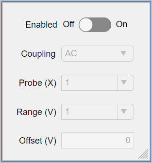
Configure Single Channel with Custom UI Component
An oscilloscope has multiple channels with identical capability and the same group of configuration parameters (such as VerticalRange and VerticalCoupling). To reduce app code complexity and the number of app UI components, create a custom UI component that configures only a single channel. You can reuse the same custom UI component for each of the channels. This example app includes a custom UI Component, oscilloscopeChannel.mlapp.
Creating a custom UI component in App Designer is similar to creating an app. To integrate the component with the app:
Specify the instrument object and channel name using public properties (for example,
comp.Instrumentandcomp.ChannelName).Use the custom component
updatefunction to program the behavior of the component when the public properties change programmatically.
function update(comp)
    ...
    if isa(comp.Instrument,"instrument.Oscilloscope") && comp.Instrument.Status == "open" && comp.ChannelName ~=""
        refreshChannelProperties(comp)
    end
end
Create a custom component event. Some oscilloscope properties depend on changes in the channel configuration. For example, the oscilloscope
TriggerLevelvalue can change when the channelVerticalRangevalue changes. You can signal to the app that the channel properties have changed by creating a custom component event,ChannelPropertyChanged. Trigger the custom component event by calling thenotifyfunction when any of the channel properties change.
function CouplingDropDownValueChanged(comp, event)
    ...
    configureChannel(comp.Instrument, comp.ChannelName, propertyName, value);
    ...
    notify(comp, "ChannelPropertyChanged");
    ...
end
Create multiple channel configuration tabs programmatically, each with the custom
oscilloscopeChannelUI component, in theinitializeChannelComponentsfunction of the app. When a channel property of the custom UI component changes, update the trigger properties using theChannelPropertyChangedFcncallback.
function initializeChannelComponents(app)
    ...
    for ii = 1:numChannels
        tabName = "TabChannel" + ii;
        componentName = "Channel" + ii;
        app.(tabName) = uitab(app.TabGroup,Title=channelNames(ii),Tag=componentName);
        app.(componentName) = oscilloscopeChannel(Parent=app.(tabName),Instrument=app.Instrument);
        ...
        app.(componentName).ChannelPropertyChangedFcn = @(src,event) refreshTriggerProperties(app);
    end
    ...
end
Read Waveform Data
Read waveform data using the oscilloscope readWaveform function. Read data when a user clicks the Read Waveform button using the ReadWaveformButtonPushed callback. For reusability, create a readWaveformTimetable function that reads the waveform data for the enabled channels, calculates the waveform timestamps, and returns a timetable. Save the waveform data to the workspace using the assignin function.
function ReadWaveformButtonPushed(app, event)
    ...
    TT = readWaveformTimetable(app, app.Instrument);
    assignin("base", app.WorkspacevariableEditField.Value, TT);
    ...
end

function TT = readWaveformTimetable(~,s)
    ...
    waveformData = cell(numChannelsEnabled,1);
    [waveformData{:}] = readWaveform(s,acquisition=true);
    y = vertcat(waveformData{:}).';
    ...
    timestamps = linspace(0,acquisitionTime,waveFormLength).' + triggerDelay;
    ...
    waveformTable = array2table(y,VariableNames=channelVariableNames);
    waveformTimetable = table2timetable(waveformTable,RowTimes=seconds(timestamps));
end
Visualize Waveform Data
Display the acquired waveform data by using the plot function. Plot the data when a user clicks the Read Waveform button or when the live plot switch is on.
function plotWaveforms(app, TT)
    ...
    plot(app.UIAxes, TT.Time, TT.Variables)
    xlim(app.UIAxes, [TT.Time(1) TT.Time(end)])
    legend(app.UIAxes, app.Instrument.ChannelsEnabled)
    ...
end
Read and Plot Data Periodically
When a user sets the live plot switch to on, read and plot data whenever the app acquires new data from the instrument. Create a startLivePlot function and use a timer object, which executes a TimerFcn callback function at a specified period.
function startLivePlot(app)
    ...
    app.LivePlotTimer = timer(...
        Period = app.LivePlotPeriodSpinner.Value,...
        ExecutionMode = "fixedRate",...
        BusyMode = "error",...
        TasksToExecute = inf,...
        TimerFcn = @(obj,event) LivePlotTimerFcn(app,obj,event),...
        ErrorFcn = @(obj,event) LivePlotTimerErrorFcn(app,obj,event));

    start(app.LivePlotTimer)
end
Create the timer callback function as an app function which reads waveform data from the instrument and plots it in the predefined app UIAxes.
function LivePlotTimerFcn(app,~,~)
    ...
    TT = readWaveformTimetable(app,app.Instrument);
    plotWaveforms(app, TT)
    ...
end
Display Errors in App
You can display errors as alerts in the app instead of displaying errors in the Command Window. Use try/catch blocks and the uialert function. For example:
function ConnectButtonPushed(app, event)
    ...
    try
        app.Instrument.Resource = app.ResourceDropDown.Value;
        app.Instrument.Driver = app.DriverDropDown.Value;
        connect(app.Instrument);
        ...
    catch exception
        ...
        mymessage = 'Verify that the Resource and Driver names you provided are valid.';
        uialert(app.OscilloscopeAppExampleUIFigure, {exception.message, mymessage}, 'Connection error');
        return
    end
    ...
end
Run App
After designing and programming the app, run the app using the Run button in App Designer. In the app, select an oscilloscope and driver to connect to. Then configure the instrument and turn the live plot on or click the Read Waveform button to read and display data from the oscilloscope.