Add a Value Change Dump (VCD) File
Introduction to the To VCD File Block
A value change dump (VCD) file logs changes to variable values, such as the values of signals, in a file during a simulation session. VCD files can be useful during design verification. Some examples of how you might apply VCD files include the following cases:
For comparing results of multiple simulation runs, using the same or different simulator environments
As input to post-simulation analysis tools
For porting areas of an existing design to a new design
VCD files can provide data that you might not otherwise acquire unless you understood the details of a device's internal logic. In addition, they include data that can be graphically displayed or analyzed with post processing tools, including, for example, the extraction of data about a particular section of a design hierarchy or data generated during a specific time interval.
Another example, this specifically for ModelSim™ users,
is the ModelSim vcd2wlf tool, which converts
a VCD file to a Wave Log Format (WLF) file that you can view in a ModelSim wave window.
The To VCD File block provided in the HDL Verifier™ block library serves as a VCD file generator during Simulink® sessions. The block generates a VCD file that contains information about changes to signals connected to the block's input ports and names the file with a specified file name.
Note
The To VCD File block logs changes to states '1' and '0' only.
The block does not log changes to states 'X' and 'Z'.
Using the To VCD File Block
To generate a VCD file, perform the following steps:
Open your Simulink model, if it is not already open.
Identify where you want to add the To VCD File block. For example, you might temporarily replace a scope with this block.
In the Simulink Library Browser, click HDL Verifier and then select the block library for your HDL simulator. You will see the HDL Cosimulation block icon and the To VCD File block icon.

Copy the To VCD File block from the Library Browser to your model by clicking the block and dragging it from the browser to your model window.
Connect the block ports to the applicable blocks in your Simulink model.
Note
Because multidimensional signals are not part of the VCD specification, they are flattened to a 1-D vector in the file.
Configure the To VCD File block by specifying values for parameters in the Block Parameters dialog box, as follows:
Double-click the block icon. Simulink displays the following dialog box.
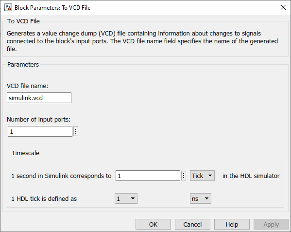
Specify a file name for the generated VCD file in the VCD file name text box.
If you specify a file name only, Simulink places the file in your current MATLAB® folder.
Specify a complete path name to place the generated file in a different location.
If you want the generated file to have a
.vcdfile type extension, you must specify it explicitly.
Note
Do not give the same file name to different VCD blocks. Doing so results in invalid VCD files.
Specify an integer in the Number of input ports text box that indicates the number of block input ports on which signal data is to be collected. The block can handle up to 943 (830,584) signals, each of which maps to a unique symbol in the VCD file.
Click OK.
Choose a timing relationship between Simulink and the HDL simulator. The time scale options specify a correspondence between one second of Simulink time and some quantity of HDL simulator time. Choose relative time or absolute time. For more on the To VCD File time scale, see the reference documentation for the To VCD File block.
Run the simulation. Simulink captures the simulation data in the VCD file as the simulation runs.
For a description of the VCD file format see VCD File Format. For a sample application of a VCD file, see Visually Compare Simulink Signals with HDL Signals.