Manual Hardware Setup
R2026bYou can use FPGA-in-the-loop (FIL), FPGA data capture, or AXI manager via Ethernet, JTAG, and PCI Express® connections. You can use FIL or AXI manager via USB Ethernet connection for an AMD® Zynq® board. Some FPGA boards support multiple connection methods, and some boards support only one method. Choose setup instructions based on the connection method you plan to use for FIL simulation.
When possible, use the guided setup. To run the support package setup, or modify your installation:
On the MATLAB® Home tab, in the Environment section, select Help > Check for Updates.
For more about the guided setup, see Set Up AMD FPGA and SoC Devices (SoC Blockset).
Step 1. Set Up FPGA Development Board
JTAG or Ethernet Connection
Make sure that the board power switch is OFF during these setup steps.
Make sure that all jumpers on the FPGA development board are in the factory default position.
Connect the AC power cord to the power plug.
Plug the power supply adapter cable into the FPGA development board.
Connect the JTAG cable to the FPGA development board and the computer. When you use Ethernet for FIL simulation, the JTAG cable is still required to program the FPGA.
If you plan to use an Ethernet connection for FIL simulation, connect the crossover Ethernet cable between the FPGA development board and the Ethernet adapter on your computer.
Turn on the power switch on the FPGA board.
PCI Express Connection
Make sure that the board power switch is OFF during these setup steps.
Select the maximum number of PCI Express (PCIe) lanes supported by the board. to Refer to the user manual for the board for details.
Supported Board PCI Express Setup Documentation DSP Development Kit, Stratix® V Edition Set the three switches (PCIE_PRSNT2nx1, x4, x8) in dip switch SW6 to ON. This setting selects 8-lane PCIe (default board setting). https://www.altera.com/products/development-kits Cyclone® V GT FPGA Development Kit Set the two switches(PCIe_x1, x4) in dip switch SW3 to ON. This setting selects 4-lane PCIe (default board setting). https://www.altera.com/products/devkit/po-3009/cyclone-v-gt-fpga-development-kit Kintex®-7 KC705 Set jumper J32 so that it connects pins 5 and 6. This setting selects 8-lane PCIe (default board setting). https://www.amd.com/en/products/adaptive-socs-and-fpgas/evaluation-boards/ek-k7-kc705-g.html Virtex®-7 VC707 Set jumper J49 so that it connects pins 5 and 6. This setting selects 8-lane PCIe (not the default board setting). https://www.amd.com/en/products/adaptive-socs-and-fpgas/evaluation-boards/ek-v7-vc707-g.html Turn off the host computer.
Install the FPGA development board in a PCI Express slot inside host computer.
For AMD boards, plug the external power supply into the wall outlet. Then plug the power supply adapter cable into the FPGA development board.
Intel® boards do not use an external power supply.
Connect the JTAG cable to the FPGA development board and the computer. When you use PCI Express for FIL simulation, the JTAG cable is still required to program the FPGA.
Turn on the power switch on the FPGA board.
Start up the host computer.
Step 2. Set Up Board Connection
assumes that there is only one download cable connected to the host computer, and that the FPGA programming software can automatically detect this connection. If not, use FPGA programming software to program your FPGA with the correct options.
JTAG Connection
Ethernet Connection
Follow these instructions to set up a Gigabit Ethernet network adapter on your computer for FIL simulation.
Open the Control Panel and type "view network connections" in the search bar. Select View network connections in the search results.
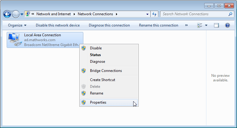
Right-click the connection icon to your FPGA development board, and select Properties from the pop-up menu.
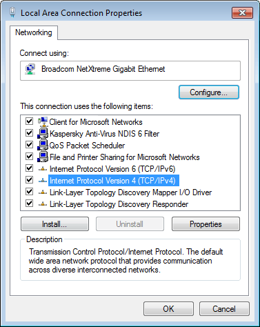
Under This connection uses the following items, select Internet Protocol Version 4 (TCP/IPv4), and click Properties.
Select Use the following IP address and set IP address to 192.168.0.1. If this address is in use by another computer on your network, change it to any available IP address on this subnet, such as 192.168.0.100. This value indicates your host computer address. Set the Subnet mask to 255.255.255.0.
The figure shows an example TCP/IP configuration.
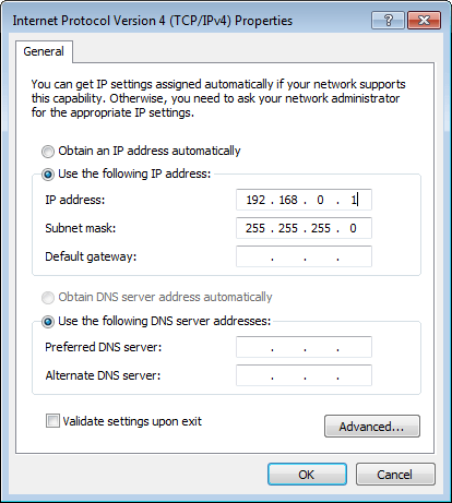
Click OK to exit TCP/IP Properties.
Click Close to exit Local Area Connection Properties.
PCI Express Connection
FIL over PCI Express connection is supported only for 64-bit Windows® operating systems.
Install the PCI Express drivers for your board using the FPGA board support package installer.
After you program your FPGA development board, restart your computer. The operating system automatically detects the new PCI Express connection. See "Step 9: Integrate and Simulate" > "Load Programming File onto FPGA" > "PCI Express Connection" under Block Generation with the FIL Wizard or System Object Generation with the FIL Wizard.

