Model Multicore Concurrent Tasking Application
This example shows a model designed and configured for generating embedded system code intended to execute as an application in a symmetric multicore, multitasking target environment. The application algorithm is captured as a multirate top model that is configured for C data interface code generation.
Periodic Multirate Model Set Up for Multitasking Concurrent Execution
Open the example model.
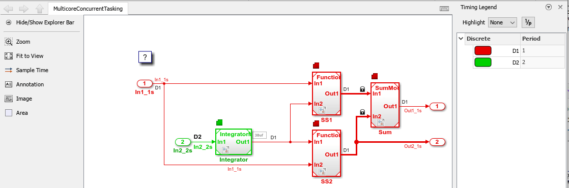
open_system('MulticoreConcurrentTasking');The model is configured to display color-coded sample times with annotations. To see them, after opening the model, update the diagram by pressing Ctrl+D. To display the legend, press Ctrl+J.
Simulink supports simulating concurrent task execution by assigning partitions of a model to tasks that you designate to run concurrently on multicore hardware. Use an implicit or explicit approach to designating partitions.
Simulink implicit partitioning:
Partitions the model based on sample times specified in the model.
Assigns a task to each sample rate and designates that the tasks run concurrently.
Controls the granularity of partitions. For example, you cannot split a sample rate into multiple tasks.
Does not impose modeling constraints.
Provides ready-to-use hardware solutions, such as solutions that the Simulink® Real-Time™ product produces.
Is not relevant to standalone production code generation due to the lack of control over partition granularity.
Explicit partitioning:
Use Model and Subsystem blocks to partition the model.
Create an arbitrary number of tasks.
Simulink assigns each partition to a task.
Simulink imposes modeling constraints.
Control the granularity of partitions.
Split a sample rate into multiple tasks.
Assign partitions to different processor cores.
Is for standalone production code generation due to the level of control you have over granularity of partitions.
This example shows explicit partitioning.
Consider the following periodic multirate model that is set up for multitasking execution.
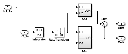
Sample times for Inport blocks
In1_1sandIn2_2sare set to 1 and 2 seconds, respectively.To provide a clear partitioning of rates, sample times for models
SS1andSS2are set to 1.The Rate Transition block explicitly models a rate transition.
To support concurrent execution of tasks in a multicore run-time environment, the preceding model was modified:
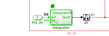
The Integrator block is in a Model block configured with a fixed-step discrete solver and a step size of two seconds.
Subsystems
SS1andSS2were converted to Model blocks configured with a fixed-step discrete solver and a step size of one second.The Sum block is in a Model block configured with a fixed-step discrete solver and a step size of one second. Another option for the Sum block is to place it in
SS1orSS2and compute its value coincident with the Model block. For concurrent execution of tasks, only connection blocks, Model blocks, and Subsystem blocks can be at the root level of a model.The Rate Transition block was removed and model configuration parameter Automatically handle rate transition for data transfer was selected. After updating the model diagram, note the 3Buf badge label above the D1 signal line. That badge label indicates where Simulink inserted a Rate Transition block during model compilation. To view the automatically inserted Rate Transition block, click the badge.
Relevant Model Configuration Parameter Settings
Type set to
Fixed-step.Solver set to
discrete (no continuous states).Treat each discrete rate as a separate task selected.
Automatically handle rate transition for data transfer selected. Necessary because Rate Transition block was removed.
Allow tasks to execute concurrently on target selected.
Concurrent Execution Parameter Settings
Open the Concurrent Execution dialog box by clicking Configure Tasks on the Configuration Parameters Solver pane. Selecting parameter Allow tasks to execute concurrently on target enables the Configure Tasks button.
When selected, parameter Enable explicit model partitioning for concurrent behavior enables concurrent execution options for the top-level model.
Click Tasks and Mapping to review the tasks and mapping.
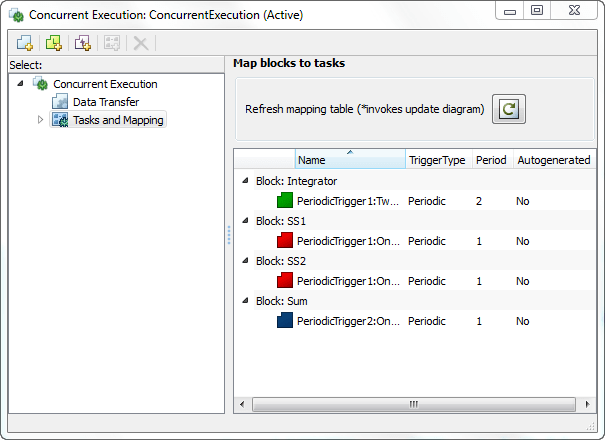
Simulink creates a default mapping for each partition (Model block) by assigning each partition to a separate task. Simulink designates that each partition executes concurrently and simulates latency effects that data communication between processor cores imposes. This dialog box displays a mapping consisting of partitions spread across two independent periodic triggers: SS1, SS2, and Sum mapped to periodic trigger 1 and Integrator mapped to periodic trigger 2.
Scheduling
Simulink® simulates the model based on the model configuration. Code generated from the model implements the same execution semantics. Simulink propagates and uses the Inport block sample times to order block execution based on a multicore, multitasking execution platform.
For this model, the sample time legend shows an implicit rate grouping. Red represents the fastest discrete rate. Green represents the second fastest discrete rate.
The generated code schedules subrates in the model. In this example, the rate for Inport block In2_2s, the green rate, is a subrate. The generated code properly transfers data between the rates.
Benefits of implicit Simulink rate grouping:
Simulink does not impose architectural constraints on the model. Create a model without imposing software architecture constraints within it.
Your execution framework does not require details about underlying function scheduling and data transfers between rates. Therefore, model interface requirements are simplified. The execution framework uses generated interface code to write input, call the model step function, and read output.
The code generator optimizes code across rates, based on multitasking execution semantics.
Simulink enforces data transfer constraints:
Data transfers occur between a single read task and a single write task.
Tasks run on a single processor.
Processes do not stop or restart, especially during data transfers between tasks.
Read and write operations on byte-sized variables are atomic.
Your execution framework can communicate with external devices for reading and writing model input. For example, model external devices by using Simulink S-Function blocks. Generate code for those blocks with the rest of the algorithm.
Generate Code and Report
Generate code and a code generation report. The example model generates a report.
Review Generated Code
From the code generation report, review the generated code.
ert_main.cis an example main program (execution framework) for the model. This code controls model code execution by indirectly calling entry-point functionsPeriodicTrigger1_OneSecond_step,PeriodicTrigger1_TwoSecond_step, andPeriodicTrigger2_OneSecond_stepwith the functionMulticoreConcurrentTasking_step. Use this file as a starting point for coding your execution framework.MulticoreConcurrentTasking.ccontains entry points for the code that implements the model algorithm. This file includes the rate and task scheduling code.MulticoreConcurrentTasking.hdeclares model data structures and a public interface to the model entry points and data structures.model_reference_types.hcontains type definitions for timing bridges. These type definitions are generated for a model reference target or a model containing Model blocks.rtw_windows.hdeclares mutex and semaphore function prototypes that the generated code uses for concurrent execution on Microsoft® Windows® platforms.rtwtypes.hdefines data types, structures, and macros that the generated code requires.
Code Interface
Open and review the Code Interface Report. Use the information in that report to write the interface code for your target platform:
Include the generated header file by adding directive
#include MulticoreConcurrentTasking.h.Write input data to the generated code for model Inport blocks.
Call the generated entry-point functions.
Read data from the generated code for model Outport blocks.
Input ports:
In1_1sof data typereal_Twith dimension of 1In2_2sof data typereal_Twith dimension of 1
Entry-point functions:
Initialization entry-point function,
void MulticoreConcurrentTasking_initialize(void). At startup, call this function once.Output and update entry-point (step) function,
void PeriodicTrigger1_OneSecond_step(void). Call this function periodically for one of two tasks that require scheduling at the fastest rate in the model. For this model, call the function every second.Output and update entry-point function,
void PeriodicTrigger1_TwoSecond_step(void). Call this function periodically at the second fastest rate in the model. For this model, call the function every two seconds.Output and update entry-point function,
void PeriodicTrigger2_OneSecond_step(void). Call this function periodically for the second task that requires scheduling at the fastest rate in the model. For this model, call the function every second.
To achieve real-time execution, define a task or thread for each entry-point step function. Trigger execution of each function based on a timer that has the same rate as the given function. The operating system schedules the tasks across cores dynamically or based on your mapping of tasks to cores.
Output ports:
Out1_1sof data typereal_Twith dimension 1Out2_1sof data typereal_Twith dimension 1