zpklp2lp
Zero-pole-gain lowpass to lowpass frequency transformation
Syntax
[Z2,P2,K2,AllpassNum,AllpassDen]
= zpklp2lp(Z,P,K,Wo,Wt)
Description
[Z2,P2,K2,AllpassNum,AllpassDen]
= zpklp2lp(Z,P,K,Wo,Wt)
returns zeros, Z2,
poles, P2, and gain factor, K2,
of the target filter transformed from the real lowpass prototype by
applying a first-order real lowpass to real lowpass frequency mapping.
This transformation effectively places one feature of an original
filter, located at frequency Wo, at the required
target frequency location, Wt.
It also returns the numerator, AllpassNum,
and the denominator, AllpassDen, of the allpass
mapping filter. The prototype lowpass filter is given with zeros, Z,
poles, P, and gain factor, K.
Relative positions of other features of an original filter do not change in the target filter. This means that it is possible to select two features of an original filter, F1 and F2, with F1 preceding F2. Feature F1 will still precede F2 after the transformation. However, the distance between F1 and F2 will not be the same before and after the transformation.
Choice of the feature subject to the lowpass to lowpass transformation is not restricted to the cutoff frequency of an original lowpass filter. In general it is possible to select any feature; e.g., the stopband edge, the DC, the deep minimum in the stopband, or other ones.
Lowpass to lowpass transformation can also be used for transforming other types of filters; e.g., notch filters or resonators can change their position in a simple way without designing them again.
Examples
Design a prototype real IIR halfband filter using a standard elliptic approach:
[b, a] = ellip(3, 0.1, 30, 0.409);
z = roots(b);
p = roots(a);
k = b(1);
[z2,p2,k2] = zpklp2lp(z, p, k, 0.5, 0.25);
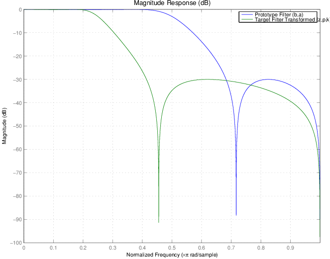
Verify the result by comparing the prototype filter with the target filter:
filterAnalyzer(b,a,k2*poly(z2),poly(p2));
Using zpklp2lp creates the desired half
band IIR filter with the transformed features that you specify in
the transformation function. This figure shows the results.
Arguments
| Variable | Description |
|---|---|
Z | Zeros of the prototype lowpass filter |
P | Poles of the prototype lowpass filter |
K | Gain factor of the prototype lowpass filter |
Wo | Frequency value to be transformed from the prototype filter |
Wt | Desired frequency location in the transformed target filter |
Z2 | Zeros of the target filter |
P2 | Poles of the target filter |
K2 | Gain factor of the target filter |
AllpassNum | Numerator of the mapping filter |
AllpassDen | Denominator of the mapping filter |
Frequencies must be normalized to be between 0 and 1, with 1 corresponding to half the sample rate.
References
Constantinides, A.G., “Spectral transformations for digital filters,” IEE Proceedings, vol. 117, no. 8, pp. 1585-1590, August 1970.
Nowrouzian, B. and A.G. Constantinides, “Prototype reference transfer function parameters in the discrete-time frequency transformations,” Proceedings 33rd Midwest Symposium on Circuits and Systems, Calgary, Canada, vol. 2, pp. 1078-1082, August 1990.
Nowrouzian, B. and L.T. Bruton, “Closed-form solutions for discrete-time elliptic transfer functions,” Proceedings of the 35th Midwest Symposium on Circuits and Systems, vol. 2, pp. 784-787, 1992.
Constantinides, A.G., “Frequency transformations for digital filters,” Electronics Letters, vol. 3, no. 11, pp. 487-489, November 1967.
Version History
Introduced in R2011a