Additive Scrambling of Input Data in Simulink
Digital communications systems commonly use additive scrambling and descrambling to randomize input data to aid in timing synchronization and meeting power spectral requirements. The Scrambler block supports multiplicative scrambling but does not support additive scrambling. To perform additive scrambling, you can use the PN Sequence Generator block. This example implements the additive scrambling specified in IEEE 802.11™ [1] by scrambling input data with an output sequence generated by the PN Sequence Generator block. For a MATLAB® example with a similar workflow, see the Additive Scrambling of Input Data example on the comm.PNSequence reference page.
This figure shows an additive scrambler, that uses the generator polynomial  , as specified in Figure 17-7 of IEEE 802.11™ Section 17.3.5.5 [1].
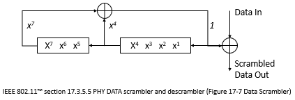
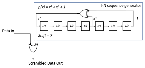
Compare the shift register specified in 802.11 with the shift register implemented using a PN Sequence Generator block and observe the two shift register schematics are mirror images of each other. Therefore, when configuring the PN Sequence Generator block to implement an additive scrambler, you must reverse values for the generator polynomial, the initial states, and the mask output. To take the output of the register from the leading end, specify a shift value of 7.
For more information about the 802.11 scrambler, see [1] and the wlanScramble (WLAN Toolbox) reference page.
The cm_additive_scrambling model scrambles and compares the generated scrambling sequence and a frame of data scrambled according to the 802.11 specified additive scrambler by using these two additive scrambler implementations:
A shift register comprised of discrete Delay (Simulink) blocks and Logical Operator (Simulink) blocks configured as XOR operators.
The PN Sequence Generator block and XOR operator.
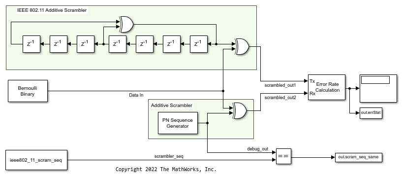
To compare the additive scrambler implementations, the cm_additive_scrambling model uses:
A Bernoulli Binary Generator block to provide an input signal to scramble.
A PN Sequence Generator block configured to use
 for the generator polynomial, [1 1 1 1 1 1 1] for the initial shift register state, and 7 for the output scrambling shift value.
A Logical Operator (Simulink) block configured as an XOR operator to apply the scramble sequence to the input data.
An Error Rate Calculation block to verify the scrambled data output from the discrete block shift register and the PN sequence versions of the additive scrambler match.
The
PreLoadFcncallback function to create a workspace variable containing the 127-bit scrambler output sequence specified in section 17.3.5.5 of the IEEE 802.11 standard. A Relational Operator (Simulink) configured for an==operation compares the 127-bit scrambler sequence as output from the Signal From Workspace block to the PN Sequence block output.
Simulate Additive Scrambling
Run the model and display the results of the error rate calculation for the scrambled input sequence and equal comparison for the scrambler sequence.
Number of errors in scrambled output comparison is 0.
Number of mismatches comparing PN sequence output to IEEE 802.11 scrambler sequence 0.
References
[1] IEEE Std 802.11™-2020 (Revision of IEEE Std 802.11-2016). "Part 11: Wireless LAN Medium Access Control (MAC) and Physical Layer (PHY) Specifications." IEEE Standard for Information technology - Telecommunications and information exchange between systems. Local and metropolitan area networks - Specific requirements.