Modeling and Analysis of Single Layer Multi-Band U-Slot Patch Antenna
The standard rectangular microstrip patch is a narrowband antenna and provides 6-8 dBi Gain with linear polarization. This example is based on the work done in [1],[2], and models a broadband patch antenna using a slot in the radiator and develops a dual-band and a tri-band variation from it. In the process, the single wide response is split into multiple narrow band regions catering to specific bands in the WiMAX standard. These patch antennas are probe-fed.
Create Single U-Slot Patch
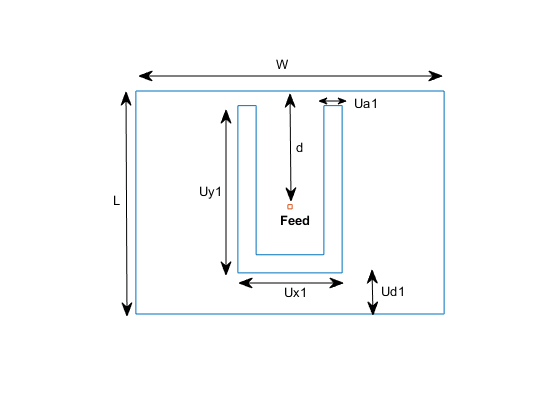
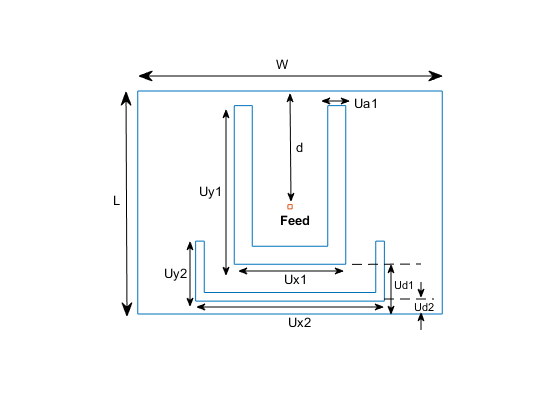
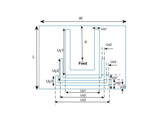
The basic U-slot patch antenna consists of a rectangular patch radiator within which a U-shaped slot is cut out. As discussed in [1], the patch itself is on an air substrate and thick enough to achieve higher bandwidths. The presence of the slot structure achieves additional capacitance within the structure which combines with the inductance of the long probe feed to create a double resonance within the band. Define the geometry parameters based on [2]. The drawing below shows these parameters.
L = 26e-3;
W = 35.5e-3;
Uy1 = 19.5e-3;
Ux1 = 12e-3;
Ua1 = 2.1e-3;
Ud1 = 4.8e-3;
d = 13.5e-3;
h = 6e-3;
Define radiator shape - Single U-slot
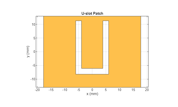
Use the rectangle shape primitives in Antenna Toolbox™ to create the U-slot patch radiator shape. Use Boolean subtraction operation between the shape primitives for this purpose.
N1 = 2;
N2 = 2;
s = antenna.Rectangle(Length=W,Width=L,NumPoints=60);
h1 = antenna.Rectangle(Length=Ua1,Width=Uy1,NumPoints=[N2 N1 N2 N1],...
    Center=[-Ux1/2 + Ua1/2, -L/2 + Ud1 + Uy1/2]);
h2 = antenna.Rectangle(Length=Ua1,Width=Uy1,NumPoints=[N2 N1 N2 N1],...
    Center=[Ux1/2 - Ua1/2, -L/2 + Ud1 + Uy1/2]);
h3 = antenna.Rectangle(Length=Ux1,Width=Ua1,NumPoints=[N1 N2 N1 N2],...
    Center=[0,-L/2 + Ud1 + Ua1/2]);
Uslot_patch = s-h1-h2-h3;
figure
show(Uslot_patch)
title("U-slot Patch")
Define ground shape
Create the ground plane shape for the antenna. The ground plane in this case is rectangular and 71 mm-by-52 mm in size.
Lgp = 71e-3;
Wgp = 52e-3;
p2 = antenna.Rectangle(Length=Lgp,Width=Wgp,NumPoints=10);
Define the layer stack
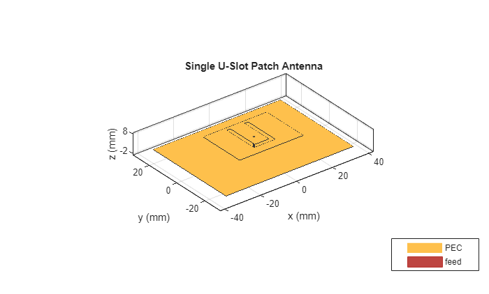
Use the pcbStack object to define the metal, dielectric layers top-down, and the feed for the single U-slot patch antenna. In this case, the top-most layer is a metal layer defined by the U-slot patch shape. The second layer is a dielectric material, air in this case, and the third layer is the metal ground plane.
d1 = dielectric("Air");
slotPatch = pcbStack;
slotPatch.Name = "U-Slot Patch";
slotPatch.BoardThickness = h;
slotPatch.BoardShape = p2;
slotPatch.Layers = {Uslot_patch,d1,p2};
slotPatch.FeedLocations = [0 L/2-d 1 3];
slotPatch.FeedDiameter = 0.9e-3;
figure
show(slotPatch)
title("Single U-Slot Patch Antenna")
Calculate and Plot Reflection Coefficient
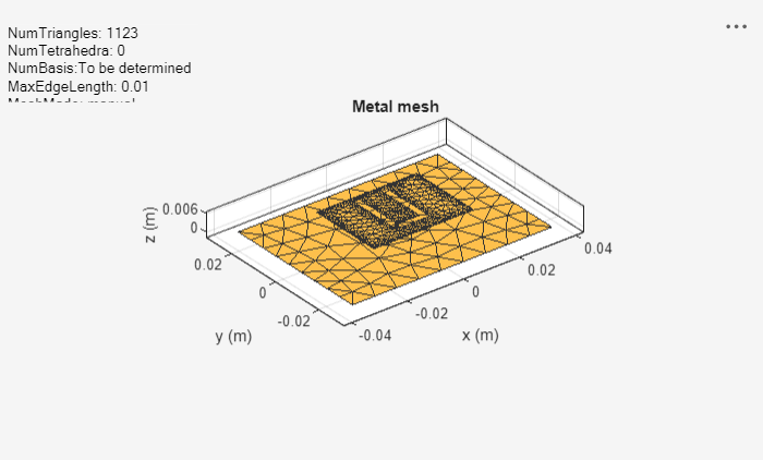
Mesh the structure by using a maximum edge length which is one-tenth the wavelength at the highest frequency of operation which is 6 GHz for this example. Compute and plot the reflection coefficient with a reference impedance of 50 ohms for this antenna over the band.
figure
mesh(slotPatch,MaxEdgeLength=0.01,MinEdgeLength=0.001,GrowthRate=0.7)
freq = linspace(3e9,6e9,200);
s1 = sparameters(slotPatch,freq);
s11Fig = figure;
rfplot(s1,1,1)
s11Ax = gca(s11Fig);
hold(s11Ax,'on');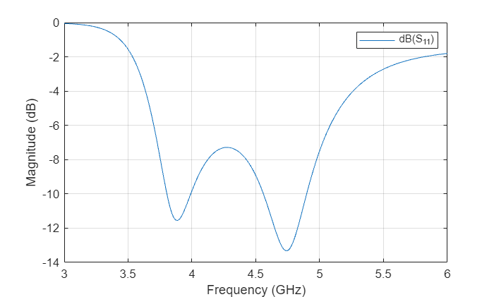
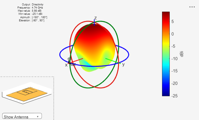
Calculate and Plot Pattern
Plot the radiation pattern for this antenna at the frequencies of best match in the band.
figure
pattern(slotPatch,3.9e9)
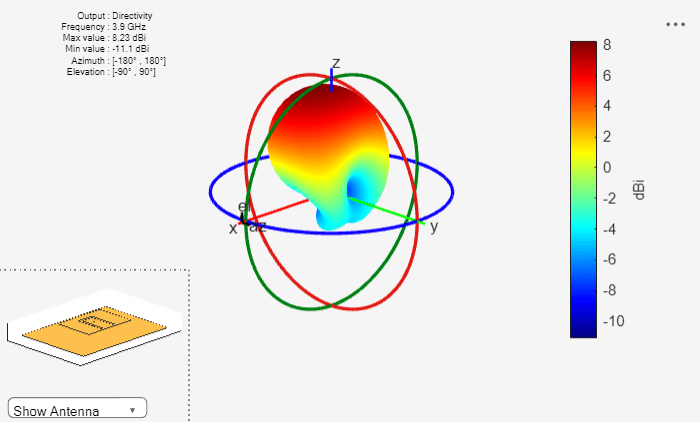
figure
pattern(slotPatch,4.74e9)
Dual-Band U-Slot Patch Antenna
To achieve dual-band behavior as shown in [1] and [2], modify the double resonance such that the two contributing resonances, from the patch and from the slot do not merge. To do so, adjust the existing slot parameters, and introduce a second slot into the structure. The parameters for the double U-slot are listed below as per [2] and a figure annotated with the variables used is shown next.
Ux1 = 13e-3;
Ux2 = 22e-3;
Uy1 = 18.5e-3;
Uy2 = 7e-3;
Ua2 = 1e-3;
Ud1 = 5.8e-3;
Ud2 = 1.5e-3;
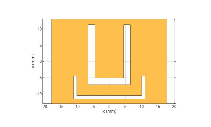
Create double U-slot radiator
Use the shape primitives, to create the geometry by using Boolean operations.
h1 = antenna.Rectangle(Length=Ua1,Width=Uy1,NumPoints=[N2 N1 N2 N1],Center=[-Ux1/2 + Ua1/2, -L/2 + Ud1 + Uy1/2]);
h2 = antenna.Rectangle(Length=Ua1,Width=Uy1,NumPoints=[N2 N1 N2 N1],Center=[Ux1/2 - Ua1/2, -L/2 + Ud1 + Uy1/2]);
h3 = antenna.Rectangle(Length=Ux1,Width=Ua1,NumPoints=[N1 N2 N1 N2],Center=[0,-L/2 + Ud1 + Ua1/2]);
Uslot_patch = s - h1 - h2 - h3;
h4 = antenna.Rectangle(Length=Ua2,Width=Uy2,NumPoints=[N2 N1 N2 N1],Center=[-Ux2/2 + Ua2/2, -L/2 + Ud2 + Uy2/2]);
h5 = antenna.Rectangle(Length=Ua2,Width=Uy2,NumPoints=[N2 N1 N2 N1],Center=[Ux2/2 - Ua2/2, -L/2 + Ud2 + Uy2/2]);
h6 = antenna.Rectangle(Length=Ux2,Width=Ua2,NumPoints=[N1 N2 N1 N2],Center=[0,-L/2 + Ud2 + Ua2/2]);
DoubleUslot_patch = Uslot_patch - h4 - h5 - h6;
figure
show(DoubleUslot_patch)
Modify layers in stack
Modify the existing stack by introducing the new radiator in the Layers property.
slotPatch.Layers = {DoubleUslot_patch,d1,p2};
figure
show(slotPatch)
title("Dual-Band U-Slot Patch Antenna")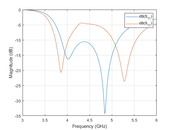
Mesh and Plot Reflection Coefficient
Mesh the structure at the highest frequency of operation and plot the reflection coefficient.
figure
mesh(slotPatch,MaxEdgeLength=0.01,MinEdgeLength=0.001,GrowthRate=0.5)
s2 = sparameters(slotPatch,freq);
figure(s11Fig);
rfplot(s2,1,1);
Triple-Band U-slot Patch Antenna
For triple-band operation, introduce a third U-slot, and adjust the existing slot parameters [2].
d = 14.5e-3;
Ux1 = 14e-3;
Ux2 = 18e-3;
Ux3 = 22e-3;
Uy1 = 18.7e-3;
Uy2 = 9e-3;
Uy3 = 4e-3;
Ud2 = 3.5e-3;
Ud3 = 1.5e-3;
Ua1 = 2e-3;
Ua3 = 1e-3;
Create the triple U-slot radiator.
N1 = 20;
N2 = 10;
h1 = antenna.Rectangle(Length=Ua1,Width=Uy1,NumPoints=[N2 N1 N2 N1],Center=[-Ux1/2 + Ua1/2, -L/2 + Ud1 + Uy1/2]);
h2 = antenna.Rectangle(Length=Ua1,Width=Uy1,NumPoints=[N2 N1 N2 N1],Center=[Ux1/2 - Ua1/2, -L/2 + Ud1 + Uy1/2]);
h3 = antenna.Rectangle(Length=Ux1,Width=Ua1,NumPoints=[N1 N2 N1 N2],Center=[0,-L/2 + Ud1 + Ua1/2]);
Uslot_patch = s - h1 - h2 - h3;
h4 = antenna.Rectangle(Length=Ua2,Width=Uy2,NumPoints=[N2 N1 N2 N1],Center=[-Ux2/2 + Ua2/2, -L/2 + Ud2 + Uy2/2]);
h5 = antenna.Rectangle(Length=Ua2,Width=Uy2,NumPoints=[N2 N1 N2 N1],Center=[Ux2/2 - Ua2/2, -L/2 + Ud2 + Uy2/2]);
h6 = antenna.Rectangle(Length=Ux2,Width=Ua2,NumPoints=[N1 N2 N1 N2],Center=[0,-L/2 + Ud2 + Ua2/2]);
DoubleUslot_patch = Uslot_patch - h4 - h5 - h6;
h7 = antenna.Rectangle(Length=Ua3,Width=Uy3,NumPoints=[N2 N1 N2 N1],Center=[-Ux3/2 + Ua3/2, -L/2 + Ud3 + Uy3/2]);
h8 = antenna.Rectangle(Length=Ua3,Width=Uy3,NumPoints=[N2 N1 N2 N1],Center=[Ux3/2 - Ua3/2, -L/2 + Ud3 + Uy3/2]);
h9 = antenna.Rectangle(Length=Ux3,Width=Ua3,NumPoints=[N1 N2 N1 N2],Center=[0,-L/2 + Ud3 + Ua3/2]);
TripleUslot_patch = DoubleUslot_patch - h7 - h8 - h9;
figure
show(TripleUslot_patch)
title("Triple U-slot Patch")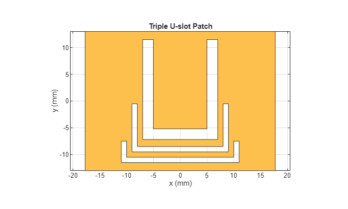
Modify the layers in the stack.
slotPatch.Layers = {TripleUslot_patch,d1,p2};
slotPatch.FeedLocations = [0 L/2-d 1 3];
figure
show(slotPatch)
title("Triple-Band U-Slot Patch Antenna")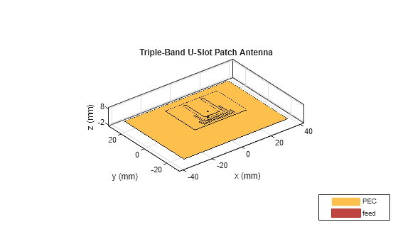
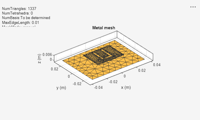
Mesh and Plot Reflection Coefficient
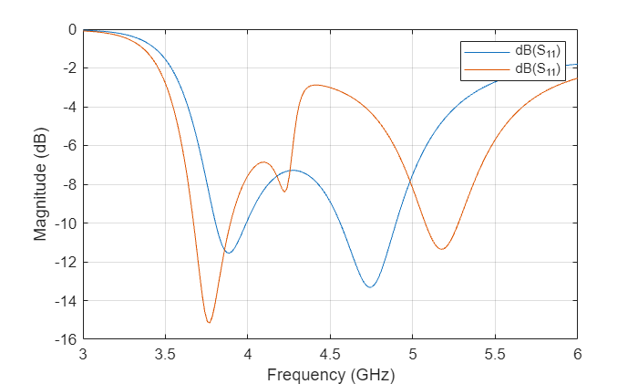
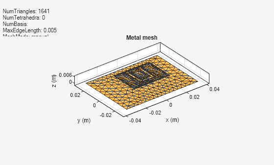
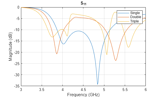
Mesh the structure and plot the reflection coefficient.
figure
mesh(slotPatch,MaxEdgeLength=0.005,MinEdgeLength=0.001,GrowthRate=0.7)
s3 = sparameters(slotPatch,freq);
figure(s11Fig)
rfplot(s3,1,1)
legend("Single","Double","Triple")
title("S_1_1")
Conclusion
The models of the multi-band single layer U-slot patch antenna as discussed in [1], and [2] are built, analyzed and agree well with results reported.
Reference
[1] Lee, Kai Fang, Shing Lung Steven Yang, Ahmed A. Kishk, and Kwai Man Luk. “The Versatile U-Slot Patch Antenna.” IEEE Antennas and Propagation Magazine 52, no. 1 (February 2010): 71–88. https://doi.org/10.1109/MAP.2010.5466402.
[2] Mok, Wing Chi, Sai Hoi Wong, Kwai Man Luk, and Kai Fong Lee. “Single-Layer Single-Patch Dual-Band and Triple-Band Patch Antennas.” IEEE Transactions on Antennas and Propagation 61, no. 8 (August 2013): 4341–44. https://doi.org/10.1109/TAP.2013.2260516.