Getting Started with PX4 Analog Input Block for ADC Channels
This example shows you how to use the PX4 Analog Input block to read the voltage applied at the ADC pins on the Pixhawk® Series controller.
Introduction
UAV Toolbox Support Package for PX4 Autopilots enables you to create Simulink® models that read the voltage applied at the ADC pins on a Pixhawk Series controller.
A single PX4 Analog Input block measures the analog voltage at all the ADC channels on the Pixhawk Series controller, based on the supported FMU version of the hardware. The block outputs the voltages as a 1-by-12 array. Each value in the array corresponds to the analog voltage at a particular channel number.
In this example, you will learn how to use the PX4 Analog Input block to:
Observe the analog voltage at all channels
Detect which of the ADC channels of the FMU are exposed on the connected PX4 flight controller, and use the voltages from those channels only in the Simulink model.
Prerequisites
If you are new to Simulink, watch the Simulink Quick Start video.
Perform the initial Install Support for UAV Toolbox Support Package for PX4 Autopilots of the support package using Hardware Setup screens.
Required Hardware
To run this example, you will need the following hardware:
Pixhawk Series flight controller
Micro USB type-B cable
4-pin cable or any cable compatible with the ADC pins on the Pixhawk Series controller
Micro-SD card (already used during the Performing PX4 System Startup from SD Card)
Task 1 - Observe ADC Channel Values
In this task, you will configure a PX4 Analog Input block to output analog data for all the ADC channels that are present on the FMU. All the ADC channels that are available on the FMU might not be exposed on the Pixhawk Series controller.
1. From the MATLAB® toolstrip, select HOME > New > Simulink Model to open the Simulink Start Page. Click Blank Model to launch a new Simulink model.
2. On the Simulink toolbar, select View > Library Browser to open the Simulink Library Browser. Click the UAV Toolbox Support Package for PX4® Autopilots tab (you can also type px4lib in MATLAB command window).

3. Drag and drop a PX4 Analog Input block to the model.
4. From the Simulink > Sinks tab in the Library Browser, drag and drop a Display block to the model. Connect the output of the PX4 Analog Input block to the Display block.

5. Connect the Pixhawk Series controller to the host computer using the USB cable.
6. In the Modeling tab of the Simulink toolstrip, click Model Settings.
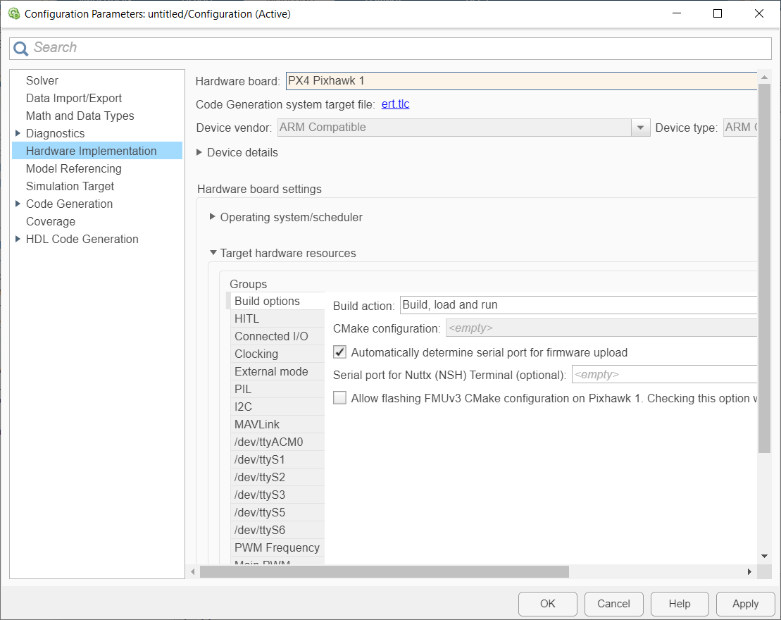
7. In the Configuration Parameters dialog box, navigate to the Hardware Implementation pane:
Set the Hardware board to the same Pixhawk series controller that you selected during Hardware Setup screens.
In the Target Hardware Resources section, enter the serial port of the host computer to which the Pixhawk Series controller is connected, in the Serial port for firmware upload field.
Click Apply and then OK.
8. In the Simulation tab, specify the stop time for parameter tuning simulation. The default value for the Stop time parameter is 10.0 seconds. To run the model for an indefinite period, enter inf.
9. Run the model using one of the following options.
Monitor & Tune: To run the model for signal monitoring and parameter tuning, on the Hardware tab, in the Mode section, select Run on board and then click Monitor & Tune to start signal monitoring and parameter tuning.

Wait for the code generation to be completed. Whenever the dialog box appears instructing you to reconnect the flight controller to the serial port, click OK and then reconnect the PX4 Autopilot on the host computer.

The lower left corner of the model window displays status while Simulink prepares, downloads, and runs the model on the hardware.
Connected IO: To run this model in the Connected I/O mode, on the Hardware tab, in the Mode section, select Connected IO and then click Run with IO.
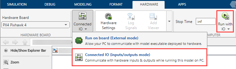
If the Connected IO firmware is not deployed on the hardware, then the a dialog box instructs you to reconnect the flight controller to the serial port appears. If the dialog box appears, click OK and then reconnect the PX4 Autopilot on the host computer.
10. Observe the voltage array values in the Display block. It is a 1-by-12 array that shows all the ADC channels based on the FMU version of the PX4 flight controller.
Task 2 - Detect ADC Channels That Are Exposed on Pixhawk Series Controller
In this task, you will determine which of the ADC channels that are provided by the FMU version are exposed on the Pixhawk Series controller, and use those index values for further processing of signals.
Ensure that the Monitor and Tune process is still running (as done in Task 1) with the PX4 Analog Input block and the Display block.
1. Use the cable to connect an ADC pin on the Pixhawk Series controller to +3.3V Vcc.
2. Observe if the value for any cell in the Display block changes to +3.3V approximately.
The index of this cell in the array is the index of ADC channel that is exposed on the flight controller.
3. Repeat steps 1 and 2 for all the other ADC channels that might be remaining in the Pixhawk Series controller.
After you identify the index numbers of all exposed ADC channels, you can stop Monitor and Tune process and remove the Display block connected at the output of the PX4 Analog Input block. You can now proceed with extracting the signal values from the block.
4. From the Simulink > Signal Routing tab in the Library Browser, drag and drop a Selector block to the model.
5. Double-click the block, and set the Input port size to 12. Set the value for Index based on the index values that you identified. For example, you can enter the Index values as [6 7 8].
6. Connect the input of the Selector block to the output of the PX4 Analog Input block.
7. Connect the output of the Selector block to a Demux block. The Number of ports in the Demux block can be set to the total number of ADC channels identified.
The output of the Demux block can be used for further processing of logic.
The complete model will look like the pre-configured model (px4demo_ADC) available for your convenience.

See Also
You can also select a web site from the following list:
Americas
- América Latina (Español)
- Canada (English)
- United States (English)
Europe
- Belgium (English)
- Denmark (English)
- Deutschland (Deutsch)
- España (Español)
- Finland (English)
- France (Français)
- Ireland (English)
- Italia (Italiano)
- Luxembourg (English)
- Netherlands (English)
- Norway (English)
- Österreich (Deutsch)
- Portugal (English)
- Sweden (English)
- Switzerland
- United Kingdom (English)