Trigger Downstream Function-Call Subsystem Using STMicroelectronics Nucleo External Interrupt Block with Data Ready Event on BMI160 Sensor
This example shows how to use the Simulink® Coder™ Support Package for STMicroelectronics® Nucleo Boards to trigger a downstream function-call in Monitor and Tune action when a Data ready event occurs on BMI160 sensor using a ST Nucleo External Interrupt block. This example model for monitor and tune simulation, shows the capabilities of the External Interrupt block during data ready event on BMI160 sensor.
When you use the Monitor and Tune (External mode) action, a data ready event occuring on BMI160 sensor provides simulation to the STMicroelectronics Nucleo board digital pin externally. For every rising edge of this input pulse signal, the downstream function-call subsystem is triggered.
Prerequisite
Completing the following examples:
Required Hardware
To run this example, you will need the following hardware:
Supported STMicroelectronics Nucleo board
BMI160 Boosterpack
USB cables
Configure Simulink Model for Reading Data from BMI160 Sensor
For the monitor and tune action (external mode), this example uses a preconfigured Simulink model from the Simulink Coder Support Package for STMicroelectronics Nucleo Boards.
To open the Simulink model, run this command at the MATLAB Command Window:
open_system('BMI160DataReadyDetection.slx');
Configure the following parameters:
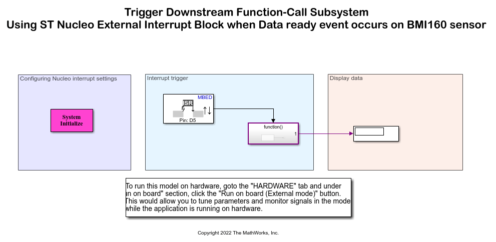
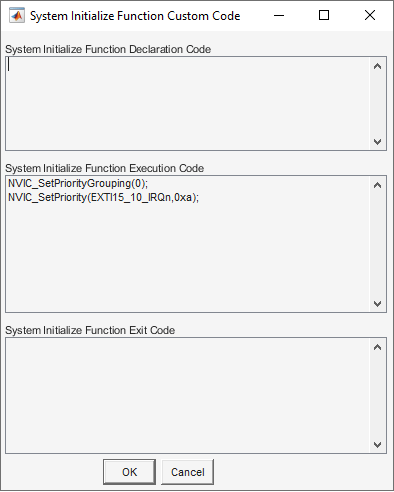
1. In the Configuring Nucleo interrupt settings area, System Initialize subsystem consists of custom code for inserting to the generated code.
2. In the Interrupt trigger area, for the BMI160 sensor ensure that Data ready option is selected for Generate interrupts on parameter.

3. Configure the External Interrupt block parameters to its default values. Ensure that the Enable simulation input option is cleared.
Signal Monitoring and Parameter Tuning
To run the model for signal monitoring and parameter tuning, on the Hardware tab, in the Mode section, select Run on board and then click Monitor & Tune to start signal monitoring and parameter tuning.
During simulation, the data ready event on the sensor generates interrupt on pin D5 of the STMicroelectronics Nucleo Board.
Observe the increment of the counter values in Display block for every rising edge of the data ready events. You can open the scope and observe the data generated output plotted against the rate transition block output.
You can notice a delay in the downstream function-call.
You can also view the output of the manual switch and rate transition block output on the Simulation Data Inspector and Logic Analyzer.
Other Things to Try
Observe the scope output for Monitor and Tune action on the falling edge (set Mode to
Fallingin the External Interrupt block) as well as both rising and falling edge (set Mode toEitherin the External Interrupt block) of the simulation signal.
You can also select a web site from the following list:
Americas
- América Latina (Español)
- Canada (English)
- United States (English)
Europe
- Belgium (English)
- Denmark (English)
- Deutschland (Deutsch)
- España (Español)
- Finland (English)
- France (Français)
- Ireland (English)
- Italia (Italiano)
- Luxembourg (English)
- Netherlands (English)
- Norway (English)
- Österreich (Deutsch)
- Portugal (English)
- Sweden (English)
- Switzerland
- United Kingdom (English)