Trigger Downstream Function-Call Subsystem Using Arduino External Interrupt Block
This example shows how to trigger a downstream function call subsystem by using an External Interrupt block from the Simulink® Support Package for Arduino® Hardware.
In this example, you will learn how to trigger the function call in Normal mode and External mode simulation.
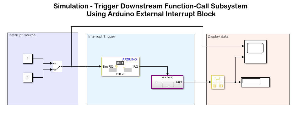
Normal mode simulation: In Normal mode, you can verify the model design by simulating an input to the External Interrupt block. The External Interrupt block receives an input value of
0or1at each time step. When the input at the block port is1, the block executes the function call subsystem. The function call increments the value of a counter by 1 each time it is triggered.
External mode simulation: In External mode, pin 4 generates a pulse-width modulation (PWM) signal at pin 2 of the hardware at each time step. When pin 2 receives a rising edge as input, the block executes the function call to increment the value of the counter.
Supported Arduino Hardware
Arduino Due
Arduino Leonardo
Arduino Mega 2560
Arduino Mega ADK
Arduino Micro
Arduino MKR1000
Arduino MKR WIFI 1010
Arduino MKR ZERO
Arduino Nano 3.0
Arduino Robot Control Board
Arduino Robot Motor Board
Arduino Uno
Arduino Nano 33 IoT
Arduino compatible ESP32 - WROOM
Arduino compatible ESP32 - WROVER
Prerequisites
Before you start this example, complete the Get Started with Arduino Hardware example.
Required Hardware
Supported Arduino board
USB cable
Breadboard wires
Step 1: Configure Simulink Model for Supported Arduino Hardware
Open the arduino_external_interrupt_sim Simulink model.
Step 2: Simulate Model
In the model, the SimIRQ port of the External Interrupt block is connected to input 0 of the Interrupt Source area. An input value of 1 indicates that the block triggers the function call to increment the counter value by 1 at each time step during simulation.
1. On the Simulation tab of the Simulink model, click Run. The lower-left corner of the model window displays status while Simulink prepares to run the Simulink model on the computer.
2. Now toggle the Interrupt Source to input 1. Counter value gets incremented as long as SimIRQ is 1.
Step 3: Run Simulink Model in External mode (Monitor and Tune)
1. Open the arduino_external_interrupt Simulink model.

This model is preconfigured to run on Arduino Mega 2560. If you are using Arduino Mega 2560, skip the remaining steps in this section.
2. On the model toolbar, click the Model Configuration Parameters button.
3. In the Configurations Parameters dialog box, select Hardware Implementation.
4. From the Hardware board list, select the type of Arduino hardware that you are using. Do not change any other settings.
5. Click OK.
6. Connect the pulse generator pin 4 to the external interrupt pin 2 of the hardware. For information on pin mapping on the hardware, see Pin Mapping for Arduino Timer Independent Blocks.

7. You can use this preconfigured Simulink model. Otherwise, modify the model using these steps:
a. In the Simulink model toolbar, set the simulation Stop Time to 20.0 seconds.
b. Modify the Interrupt Source area of the model to generate PWM signal on pin 4 of the Arduino hardware.
c. Double-click the External Interrupt block and configure the block to generate an interrupt when pin 2 of the hardware receives a rising edge of the PWM signal.
    Parameter    |      Value
  _ _ _ _ _ _ _ _ _ _ _ _ _ _ _ _ _
    Pin number   |        2
    Mode         |      RISING
8. On the Hardware tab of the Simulink model, in the Mode section, select Run on board and then click Monitor & Tune. The lower-left corner of the model window displays status while Simulink prepares, downloads, and runs the Simulink model on the hardware. During simulation, pin 4 generates a PWM signal on pin 2 of the hardware. The pin 2 generates an interrupt on every rising edge of the signal as increments the counter value by 1.
9. View the changing value of the counter at each time step by double-clicking the Scope block in the Display data area of the model. On the scope, the counter value is plotted against the time value. The counter value is incremented by 1 as the value received at each time step is 1.

Other Things to Try
Change the value of the Mode parameter in the External Interrupt block and deploy the model again.
Use the signal generated from an encoder as a source for the external interrupt.
You can also select a web site from the following list:
Americas
- América Latina (Español)
- Canada (English)
- United States (English)
Europe
- Belgium (English)
- Denmark (English)
- Deutschland (Deutsch)
- España (Español)
- Finland (English)
- France (Français)
- Ireland (English)
- Italia (Italiano)
- Luxembourg (English)
- Netherlands (English)
- Norway (English)
- Österreich (Deutsch)
- Portugal (English)
- Sweden (English)
- Switzerland
- United Kingdom (English)