TuningGoal.Variance
Noise amplification constraint for control system tuning
Description
Use TuningGoal.Variance to specify a tuning goal
that limits the noise amplification from specified inputs to outputs.
The noise amplification is defined as either:
The square root of the output variance, for a unit-variance white-noise input
The root-mean-square of the output, for a unit-variance white-noise input
The H2 norm of the transfer function from the specified inputs to outputs, which equals the total energy of the impulse response
These definitions are different interpretations of the same quantity. TuningGoal.Variance imposes the same limit on these quantities.
You can use TuningGoal.Variance for control system
tuning with tuning commands, such as systune or
looptune. Specifying this tuning goal allows you to tune the system
response to white-noise inputs. For stochastic inputs with a nonuniform spectrum (colored
noise), use TuningGoal.WeightedVariance instead.
After you create a tuning goal, you can further configure the tuning goal by setting Properties of the object.
Creation
Description
Req = TuningGoal.Variance(inputname,outputname,maxamp)inputname to outputname to the scalar value
maxamp.
When you tune a control system in discrete time, this tuning goal assumes that the
physical plant and noise process are continuous. To ensure that continuous-time and
discrete-time tuning give consistent results, maxamp is interpreted
as a constraint on the continuous-time H2
norm. If the plant and noise processes are truly discrete and you want to constrain the
discrete-time H2 norm to the value
maxamp, set the third input argument to
maxamp/sqrt(Ts), where Ts
is the sample time of the model you are tuning.
Input Arguments
Input signals for the tuning goal, specified as a character vector or, for multiple-input tuning goals, a cell array of character vectors.
If you are using the tuning goal to tune a Simulink® model of a control system, then
inputnamecan include:Any model input.
Any linear analysis point marked in the model.
Any linear analysis point in an
slTuner(Simulink Control Design) interface associated with the Simulink model. UseaddPoint(Simulink Control Design) to add analysis points to theslTunerinterface. UsegetPoints(Simulink Control Design) to get the list of analysis points available in anslTunerinterface to your model.
For example, suppose that the
slTunerinterface contains analysis pointsu1andu2. Use'u1'to designate that point as an input signal when creating tuning goals. Use{'u1','u2'}to designate a two-channel input.
If you are using the tuning goal to tune a generalized state-space (
genss) model of a control system, theninputnamecan include:Any input of the
genssmodelAny
AnalysisPointlocation in the control system model
For example, if you are tuning a control system model,
T, theninputnamecan be any input name inT.InputName. Also, ifTcontains anAnalysisPointblock with a location namedAP_u, theninputnamecan include'AP_u'. UsegetPointsto get a list of analysis points available in agenssmodel.If
inputnameis anAnalysisPointlocation of a generalized model, the input signal for the tuning goal is the implied input associated with theAnalysisPointblock: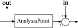
For more information about analysis points in control system models, see Mark Signals of Interest for Control System Analysis and Design.
Output signals for the tuning goal, specified as a character vector or, for multiple-output tuning goals, a cell array of character vectors.
If you are using the tuning goal to tune a Simulink model of a control system, then
outputnamecan include:Any model output.
Any linear analysis point marked in the model.
Any linear analysis point in an
slTuner(Simulink Control Design) interface associated with the Simulink model. UseaddPoint(Simulink Control Design) to add analysis points to theslTunerinterface. UsegetPoints(Simulink Control Design) to get the list of analysis points available in anslTunerinterface to your model.
For example, suppose that the
slTunerinterface contains analysis pointsy1andy2. Use'y1'to designate that point as an output signal when creating tuning goals. Use{'y1','y2'}to designate a two-channel output.
If you are using the tuning goal to tune a generalized state-space (
genss) model of a control system, thenoutputnamecan include:Any output of the
genssmodelAny
AnalysisPointlocation in the control system model
For example, if you are tuning a control system model,
T, thenoutputnamecan be any output name inT.OutputName. Also, ifTcontains anAnalysisPointblock with a location namedAP_u, thenoutputnamecan include'AP_u'. UsegetPointsto get a list of analysis points available in agenssmodel.If
outputnameis anAnalysisPointlocation of a generalized model, the output signal for the tuning goal is the implied output associated with theAnalysisPointblock:
For more information about analysis points in control system models, see Mark Signals of Interest for Control System Analysis and Design.
maxamp — Maximum noise amplification from inputname to
outputname
positive scalar
Maximum noise amplification from inputname to
outputname, specified as a positive scalar value. This value
specifies the maximum value of the output variance at the signals specified in
outputname, for unit-variance white noise signal at
inputname. This value corresponds to the maximum
H2 norm from
inputname to outputname.
When you tune a control system in discrete time, this tuning goal assumes that the
physical plant and noise process are continuous, and interprets
maxamp as a bound on the continuous-time
H2 norm. This ensures that continuous-time
and discrete-time tuning give consistent results. If the plant and noise processes are
truly discrete, and you want to bound the discrete-time
H2 norm instead, specify the value
maxamp/. Ts is the sample time of
the model you are tuning.
Properties
Examples
Constrain Noise Amplification Evaluated with a Loop Opening
Create a requirement that constrains the amplification of the variance from the analysis point AP2 to the output y of the following control system, measured with the outer loop open.
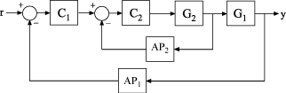
Create a model of the system. To do so, specify and connect the numeric plant models G1 and G2, and the tunable controllers C1 and C2. Also specify and connect the AnalysisPoint blocks AP1 and AP2 that mark points of interest for analysis and tuning.
G1 = tf(10,[1 10]);
G2 = tf([1 2],[1 0.2 10]);
C1 = tunablePID('C','pi');
C2 = tunableGain('G',1);
AP1 = AnalysisPoint('AP1');
AP2 = AnalysisPoint('AP2');
T = feedback(G1*feedback(G2*C2,AP2)*C1,AP1);
Create a tuning requirement that constrains the noise amplification from the implicit input associated with the analysis point, AP2, to the output y.
Req = TuningGoal.Variance('AP2','y',0.1);
This constraint limits the amplification to a factor of 0.1.
Specify that the transfer function from AP2 to y is evaluated with the outer loop open when tuning to this constraint.
Req.Openings = {'AP1'};Use systune to tune the free parameters of T to meet the tuning requirement specified by Req. You can then validate the tuned control system against the requirement using viewGoal(Req,T).
Tips
When you use this tuning goal to tune a continuous-time control system,
systuneattempts to enforce zero feedthrough (D = 0) on the transfer that the tuning goal constrains. Zero feedthrough is imposed because the H2 norm, and therefore the value of the tuning goal (see Algorithms), is infinite for continuous-time systems with nonzero feedthrough.systuneenforces zero feedthrough by fixing to zero all tunable parameters that contribute to the feedthrough term.systunereturns an error when fixing these tunable parameters is insufficient to enforce zero feedthrough. In such cases, you must modify the tuning goal or the control structure, or manually fix some tunable parameters of your system to values that eliminate the feedthrough term.When the constrained transfer function has several tunable blocks in series, the software’s approach of zeroing all parameters that contribute to the overall feedthrough might be conservative. In that case, it is sufficient to zero the feedthrough term of one of the blocks. If you want to control which block has feedthrough fixed to zero, you can manually fix the feedthrough of the tuned block of your choice.
To fix parameters of tunable blocks to specified values, use the
ValueandFreeproperties of the block parametrization. For example, consider a tuned state-space block:C = tunableSS('C',1,2,3);To enforce zero feedthrough on this block, set its D matrix value to zero, and fix the parameter.
C.D.Value = 0;
C.D.Free = false;
For more information on fixing parameter values, see the Control Design Block reference pages, such as
tunableSS.This tuning goal imposes an implicit stability constraint on the closed-loop transfer function from
InputtoOutput, evaluated with loops opened at the points identified inOpenings. The dynamics affected by this implicit constraint are the stabilized dynamics for this tuning goal. TheMinDecayandMaxRadiusoptions ofsystuneOptionscontrol the bounds on these implicitly constrained dynamics. If the optimization fails to meet the default bounds, or if the default bounds conflict with other requirements, usesystuneOptionsto change these defaults.
Algorithms
When you tune a control system using a TuningGoal, the software
converts the tuning goal into a normalized scalar value
f(x). The vector x is the vector of
free (tunable) parameters in the control system. The software then adjusts the parameter
values to minimize f(x) or to drive
f(x) below 1 if the tuning goal is a hard
constraint.
For TuningGoal.Variance, f(x) is
given by:
T(s,x) is the closed-loop
transfer function from Input to Output. denotes the H2 norm (see
norm).
For tuning discrete-time control systems, f(x) is given by:
Ts is the sample time of the discrete-time transfer function T(z,x).
Version History
Introduced in R2016aSee Also
looptune | systune | looptune (for slTuner) (Simulink Control Design) | systune (for slTuner) (Simulink Control Design) | slTuner (Simulink Control Design) | viewGoal | evalGoal | norm | TuningGoal.WeightedVariance
You can also select a web site from the following list:
Americas
- América Latina (Español)
- Canada (English)
- United States (English)
Europe
- Belgium (English)
- Denmark (English)
- Deutschland (Deutsch)
- España (Español)
- Finland (English)
- France (Français)
- Ireland (English)
- Italia (Italiano)
- Luxembourg (English)
- Netherlands (English)
- Norway (English)
- Österreich (Deutsch)
- Portugal (English)
- Sweden (English)
- Switzerland
- United Kingdom (English)