TuningGoal.StepRejection
Step disturbance rejection requirement for control system tuning
Description
Use TuningGoal.StepRejection to specify how
a step disturbance injected at a specified location in your control system affects the
signal at a specified output location. Use this tuning goal with control system tuning
commands such as systune or looptune.
You can specify the desired response in time-domain terms of peak value, settling time, and damping ratio. Alternatively, you can specify the response as a stable reference model having DC-gain. In that case, the tuning goal is to reject the disturbance as well as or better than the reference model.
To specify disturbance rejection in terms of a frequency-domain attenuation profile,
use TuningGoal.Rejection.
Creation
Syntax
Description
Req = TuningGoal.StepRejection(inputname,outputname,refsys)inputname affects the response at
outputname. The tuning goal is that the disturbance
be rejected as well as or better than the reference system.
inputname and outputname can
describe a SISO or MIMO response of your control system. For MIMO responses,
the number of inputs must equal the number of outputs.
Req = TuningGoal.StepRejection(inputname,outputname,peak,tSettle)
Req = TuningGoal.StepRejection(inputname,outputname,peak,tSettle,zeta)zeta.
Input Arguments
Input signals for the tuning goal, specified as a character vector or, for multiple-input tuning goals, a cell array of character vectors.
If you are using the tuning goal to tune a Simulink® model of a control system, then
inputnamecan include:Any model input.
Any linear analysis point marked in the model.
Any linear analysis point in an
slTuner(Simulink Control Design) interface associated with the Simulink model. UseaddPoint(Simulink Control Design) to add analysis points to theslTunerinterface. UsegetPoints(Simulink Control Design) to get the list of analysis points available in anslTunerinterface to your model.
For example, suppose that the
slTunerinterface contains analysis pointsu1andu2. Use'u1'to designate that point as an input signal when creating tuning goals. Use{'u1','u2'}to designate a two-channel input.
If you are using the tuning goal to tune a generalized state-space (
genss) model of a control system, theninputnamecan include:Any input of the
genssmodelAny
AnalysisPointlocation in the control system model
For example, if you are tuning a control system model,
T, theninputnamecan be any input name inT.InputName. Also, ifTcontains anAnalysisPointblock with a location namedAP_u, theninputnamecan include'AP_u'. UsegetPointsto get a list of analysis points available in agenssmodel.If
inputnameis anAnalysisPointlocation of a generalized model, the input signal for the tuning goal is the implied input associated with theAnalysisPointblock: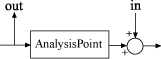
For more information about analysis points in control system models, see Mark Signals of Interest for Control System Analysis and Design.
Output signals for the tuning goal, specified as a character vector or, for multiple-output tuning goals, a cell array of character vectors.
If you are using the tuning goal to tune a Simulink model of a control system, then
outputnamecan include:Any model output.
Any linear analysis point marked in the model.
Any linear analysis point in an
slTuner(Simulink Control Design) interface associated with the Simulink model. UseaddPoint(Simulink Control Design) to add analysis points to theslTunerinterface. UsegetPoints(Simulink Control Design) to get the list of analysis points available in anslTunerinterface to your model.
For example, suppose that the
slTunerinterface contains analysis pointsy1andy2. Use'y1'to designate that point as an output signal when creating tuning goals. Use{'y1','y2'}to designate a two-channel output.
If you are using the tuning goal to tune a generalized state-space (
genss) model of a control system, thenoutputnamecan include:Any output of the
genssmodelAny
AnalysisPointlocation in the control system model
For example, if you are tuning a control system model,
T, thenoutputnamecan be any output name inT.OutputName. Also, ifTcontains anAnalysisPointblock with a location namedAP_u, thenoutputnamecan include'AP_u'. UsegetPointsto get a list of analysis points available in agenssmodel.If
outputnameis anAnalysisPointlocation of a generalized model, the output signal for the tuning goal is the implied output associated with theAnalysisPointblock:
For more information about analysis points in control system models, see Mark Signals of Interest for Control System Analysis and Design.
refsys — Reference system for target step rejection
tf model object | zpk model object | ss model object
Reference system for target step rejection, specified as a SISO
dynamic system model, such as a tf,
zpk, or ss model.
refsys must be stable and proper, and must have
zero DC gain. This restriction ensures perfect rejection of the
steady-state disturbance.
refsys can be continuous or discrete. If
refsys is discrete, it can include time delays
which are treated as poles at z = 0.
For best results, refsys and the open-loop
response from the disturbance to the output should have similar gains at
the frequency where the reference model gain peaks. You can check the
peak gain and peak frequency using getPeakGain. For
example:
[gmax,fmax] = getPeakGain(refsys);
Use getIOTransfer to
extract the corresponding open-loop response from the system you are
tuning.
peak — Peak absolute value of target response to disturbance
scalar
Peak absolute value of target response to disturbance, specified as a scalar value.
tSettle — Target settling time of response to disturbance
scalar
Target settling time of the response to disturbance, specified as a positive scalar value, in the time units of the control system you are tuning.
zeta — Minimum damping ratio of oscillations in response to disturbance
1 (default) | scalar in the range [0,1]
Minimum damping ratio of oscillations in the response to disturbance, specified as a value between 0 and 1.
Properties
Examples
Specify First-Order or Second-Order Step Disturbance Response Characteristics
Create a requirement that specifies the step disturbance response in terms of peak time-domain response, settling time, and damping of oscillations.
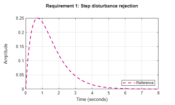
Suppose you want the response at 'y' to a disturbance injected at 'd' to never exceed an absolute value of 0.25, and to settle within 5 seconds. Create a TuningGoal.StepRejection requirement that captures these specifications and also specifies non-oscillatory response.
Req1 = TuningGoal.StepRejection('d','y',0.25,5);
Omitting an explicit value for the damping ratio, zeta, is equivalent to setting zeta = 1. Therefore, Req specifies a non-oscillatory response. The software converts the peak value and settling time into a reference transfer function whose step response has the desired time-domain profile. This transfer function is stored in the ReferenceModel property of Req.
Req1.ReferenceModel
ans =

   0.92883 s
  -----------
  (s+1.367)^2

Continuous-time zero/pole/gain model.
Confirm the target response by displaying Req.
figure()
viewGoal(Req1)
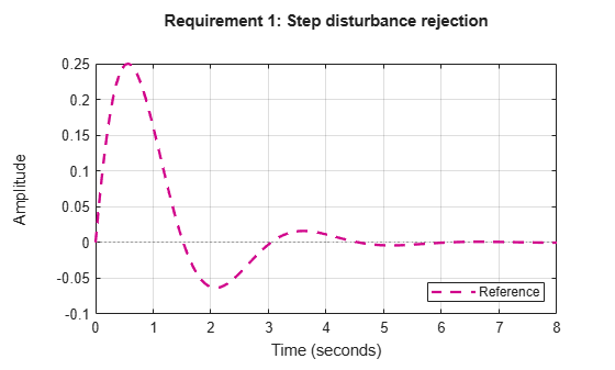
Suppose your application can tolerate oscillations provided the damping ratio is less than 0.4. Create a requirement that specifies this disturbance response.
Req2 = TuningGoal.StepRejection('d','y',0.25,5,0.4);
figure()
viewGoal(Req2)
Step Disturbance Rejection with Custom Reference Model
Create a requirement that specifies the step disturbance response as a transfer function.
Suppose you want the response to a disturbance injected at an analysis point d in your control system and measured at a point 'y' to be rejected at least as well as the transfer function
Create a TuningGoal.StepRejection requirement.
H = tf([1 0],[1 2 1]);
Req = TuningGoal.StepRejection('d','y',H);
Display the requirement.
viewGoal(Req)
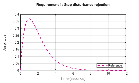
The plot displayed by viewGoal shows the step response of the specified transfer function. This response is the target time-domain response to disturbance.
Tips
This tuning goal imposes an implicit stability constraint on the closed-loop transfer function from
InputtoOutput, evaluated with loops opened at the points identified inOpenings. The dynamics affected by this implicit constraint are the stabilized dynamics for this tuning goal. TheMinDecayandMaxRadiusoptions ofsystuneOptionscontrol the bounds on these implicitly constrained dynamics. If the optimization fails to meet the default bounds, or if the default bounds conflict with other requirements, usesystuneOptionsto change these defaults.
Algorithms
When you tune a control system using a TuningGoal, the software
converts the tuning goal into a normalized scalar value
f(x), where x is the vector
of free (tunable) parameters in the control system. The software then adjusts the
parameter values to minimize f(x) or to drive
f(x) below 1 if the tuning goal is a hard
constraint.
TuningGoal.StepRejection aims to keep the gain from disturbance to
output below the gain of the reference model. The scalar value of the tuning goal
f(x) is given by:
or its discrete-time equivalent. Here,
Tdy(s,x)
is the closed-loop transfer function from Input to
Output, and denotes the H∞ norm
(see norm). WF is a
frequency weighting function derived from the step-rejection profile you specify in the
tuning goal. The gains of WF and
1/ReferenceModel roughly match for gain values within 60 dB of
the peak gain. For numerical reasons, the weighting function levels off outside this
range, unless you specify a reference model that changes slope outside this range. This
adjustment is called regularization. Because poles of
WF close to s = 0
or s = Inf might lead to poor numeric conditioning
of the systune optimization problem, it is not recommended to
specify reference models with very low-frequency or very high-frequency dynamics.
To obtain WF, use:
WF = getWeight(Req,Ts)
where Req is the tuning goal, and Ts is the
sample time at which you are tuning (Ts = 0 for continuous time). For
more information about regularization and its effects, see Visualize Tuning Goals.
Version History
Introduced in R2016aSee Also
looptune | systune | systune (for slTuner) (Simulink Control Design) | looptune (for slTuner) (Simulink Control Design) | viewGoal | evalGoal | TuningGoal.Gain | TuningGoal.LoopShape | slTuner (Simulink Control Design)
You can also select a web site from the following list:
Americas
- América Latina (Español)
- Canada (English)
- United States (English)
Europe
- Belgium (English)
- Denmark (English)
- Deutschland (Deutsch)
- España (Español)
- Finland (English)
- France (Français)
- Ireland (English)
- Italia (Italiano)
- Luxembourg (English)
- Netherlands (English)
- Norway (English)
- Österreich (Deutsch)
- Portugal (English)
- Sweden (English)
- Switzerland
- United Kingdom (English)