What Is a State Machine?
A state machine (or finite state machine) is a representation of an event-driven, reactive system that transitions from one state to another if the condition that controls the change is met. State machines were conventionally used to describe computing systems, but they have been expanded to model complex logic in dynamic systems such as aircraft, automobiles, robots, and mobile phones.
Examples of operations containing complex logic include:
- Scheduling a sequence of tasks or steps for a system
- Defining fault detection, isolation, and recovery logic
- Supervising how to switch between different modes of operation
There are many ways of expressing a state machine, although a graphical approach is most common. A state transition diagram, also known as a state diagram, is a diagram showing a finite number of states with rules that govern when transitions occur from one state to another.
For example, you can use a state diagram to represent a simplified version of a car’s automatic gear transmission. The state machine shown below has four operating states labeled first, second, third, and fourth. Like the gears they represent, these states are exclusive, so only one state is active at a time. This state machine monitors the speed of the car and shifts to a different gear when the speed crosses the fixed threshold for the gear in operation.
Figure 1. State diagram of an automatic gear transmission system modeled using Stateflow.
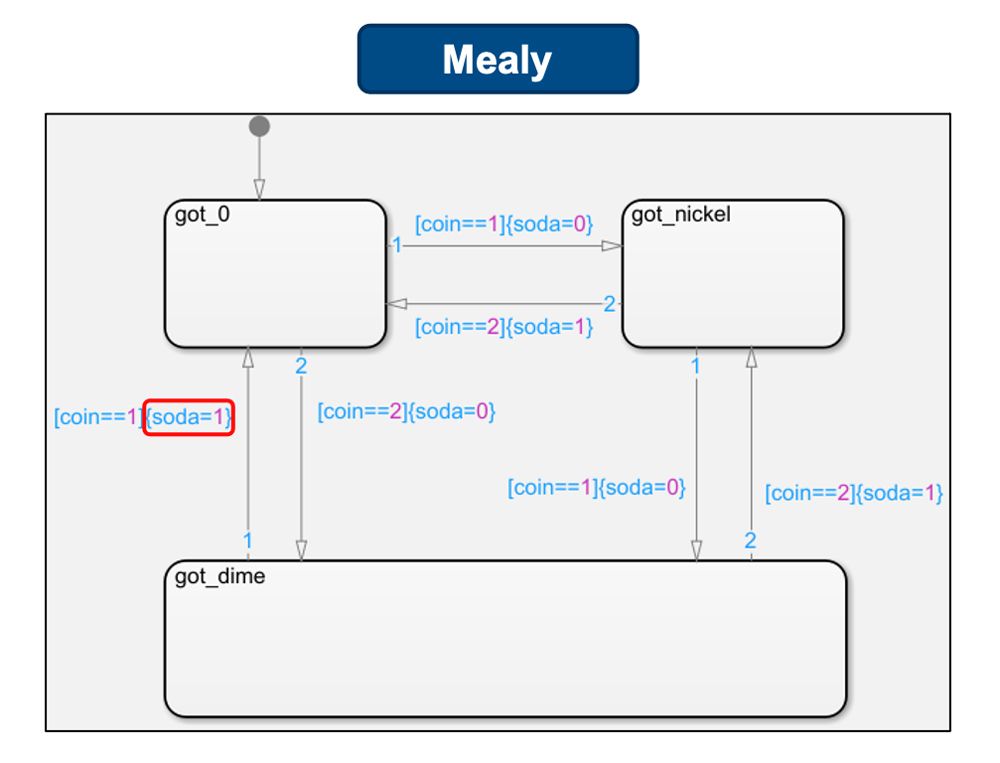
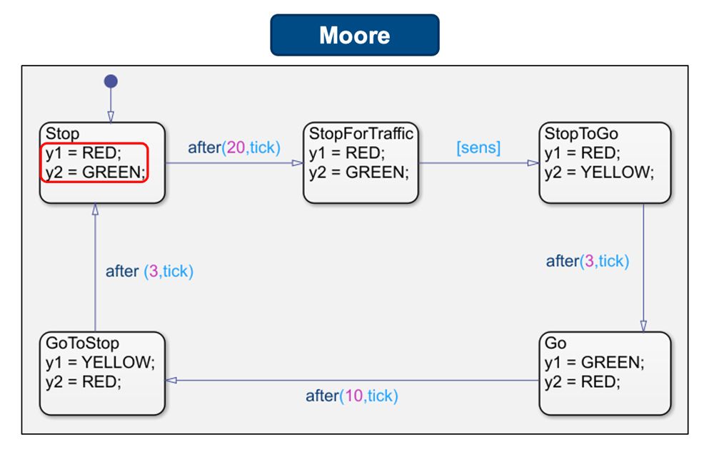
There are two main types of state diagrams:
- Mealy – State machine outputs depend not only on the states but also on inputs to the system, represented by defining machine outputs in the transitions as shown in Figure 2
- Moore – State machine outputs depend only on the state of the system, represented by defining machine outputs on the states as shown in Figure 3
For more information on these semantics, see Overview of Mealy and Moore Machines.
To create state machines that emulate a complex software component, the basic building blocks of state diagrams are not enough. The following additional capabilities are required to capture intricate details of the system efficiently:
- Hierarchy – Introduces parent state(s) and further structures the design
- Parallelism or Orthogonality – Allows for a single diagram to include multiple states operating simultaneously
- Event Broadcasting – Allows for information exchange between two independent states or state machines
When these capabilities are coupled with state transition diagrams, the representations are called Harel statecharts, or simply state charts.
Figure 4. State chart of a security system modeled using Stateflow.
For more information on these capabilities, see State Diagram and State Chart.
State Machines with Stateflow
Stateflow® is a graphical programming environment based on finite state machines. Using Stateflow, you can start from simple state diagrams and build out state charts to model complex logic in dynamic systems.
You can use MATLAB® to execute standalone state charts as MATLAB objects, or Simulink® to simulate state charts as Simulink blocks.
For more information on modeling and executing Stateflow charts in MATLAB or Simulink, see Model Finite State Machines.
To learn more about modeling state machines, see Stateflow and Simulink.
Examples and How To
Software Reference
See also: control logic, state diagram, control systems, embedded systems

또한 다음 목록에서 웹사이트를 선택하실 수도 있습니다.
미주
- América Latina (Español)
- Canada (English)
- United States (English)
유럽
- Belgium (English)
- Denmark (English)
- Deutschland (Deutsch)
- España (Español)
- Finland (English)
- France (Français)
- Ireland (English)
- Italia (Italiano)
- Luxembourg (English)
- Netherlands (English)
- Norway (English)
- Österreich (Deutsch)
- Portugal (English)
- Sweden (English)
- Switzerland
- United Kingdom (English)
아시아 태평양
- Australia (English)
- India (English)
- New Zealand (English)
- 中国
- 日本Japanese (日本語)
- 한국Korean (한국어)